An electric vehicle branch circuit is an electrical circuit in a building that supplies power to the EV charger after it branches off from the main service panel or a dedicated EV charger subpanel.
Electric vehicle branch circuts emphasizes on focusing on dedicated circuits and circuit sizing considerations when installing EV chargers in main electrical panels or dedicated EV charger subpanels.
The revised 2023 NEC language for 625.40 now requires electric vehicle branch circuits for electric vehicle charger installations that exceed 16 amperes or 120 volts, considering Level 1 EV chargers require 12–16 amps using a standard 120-volt outlet you don’t need an electric vehicle branch circuit for Level 1 EV chargers installations.
For Level 2 EV chargers that require 15–80 amps, you will require an electric vehicle branch circuit for Level 2 EV charger installations that exceed 16 amperes, you will also be required electric vehicle branch circuits for Level 3 EV chargers since they require over 100 amperes circuits.
Table of Contents
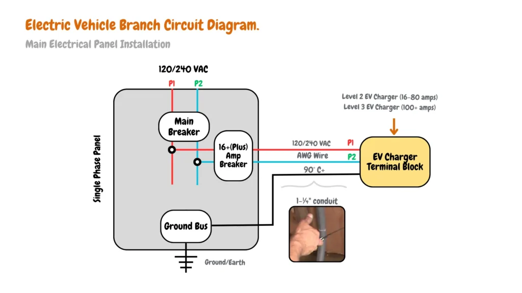
Electric Vehicle Branch Circuit Diagram.
The electric vehicle branch diagram below illustrates the electrical wiring layout for safely connecting an EV charger (16 amperes plus) to your home’s main electrical panel for a safe and code-compliant installation for your EV charger.
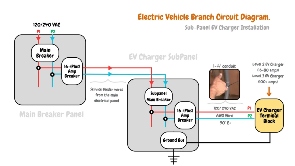
For EV charger with more than 16amps load requirements connected to an EV charger sub panel, an electric vehicle branch diagram will look similar to the diagram below:
Why Do You Need An Electric Vehicle Branch Circuit?
An electric vehicle branch circuit serves four key functions in your EV charger installations.
- An electric vehicle branch circuit allows current distribution from the electrical panel through a dedicated circuit breaker to the EV charger.
- An electric vehicle branch circuit prevents EV charger circuits from being overloaded by limiting the number of EV charger outlets and hardwire EV charger installations on each circuit.
- An electric vehicle branch circuit provides safety to the EV charger, electric vehicle charging system, and the EV charging circuit through the use of dedicated circuit breakers that trip when there is an overload or short circuit.
- An electric vehicle branch circuit allows isolations of EV Charging system faults and errors to a single circuit for easy maintenance, troubleshooting, and repair.
Components of an Electric Vehicle Branch Circuit.
A complete electric vehicle branch circuit should consist of the following:
- A hot wire that carries 120 volts of current from the electrical panel dedicated circuit breaker to the EV charger.
- A neutral wire that completes the EV charging circuit back to the electrical panel.
- A ground wire from the EV charger for safety in case of faults in the electric vehicle branch circuit.
- An electric vehicle charger connected to a dedicated circuit breaker through service wires,
- A dedicated circuit breaker in the electric main panel or the subpanel protects the circuit.
In a complete EV charger branch circuit wiring the hot and neutral wires deliver 120+V to the electric vehicle charger, while the ground wire connected to the charger protects the EV charger circuit from electric shocks by providing a safe path for electricity to flow to the ground in case of a short circuit in the EV charger circuit.
Electric Vehicle Branch Circuit Wire Sizing Requirements.
Depending on the specific EV charger amperage and the dedicated EV circuit breaker the wire sizing should be matched as follows to handle the electric load to the EV charger safely:
| EV Charger Circuit Breaker Rating | Minimum Wire Size (AWG – Copper) | Maximum Number of Conductors in Conduit |
|---|---|---|
| 15 amps | 14 Gauge Wire | 3 |
| 20 amps | 12 Gauge Wire | 3 |
| 30 amps | 10 Gauge Wire | 3 |
| 40 amps | 8 Gauge Wire | 4 |
| 50 amps | 6 Gauge Wire | 4 |
| 60 amps | 4 Gauge Wire | 4** |
| 70 amps | 2 Gauge Wire | 4** |
| 100 amps | 1 Gauge Wire | 4** |
Wiring and Installing Electric Vehicle Branch Circuit
Planning and executing a new or extended EV charger circuit goes beyond the typical steps outlined for installing general electrical circuits. Here’s why consulting a certified EV charger installer is crucial:
The Role of Certified Installers
- Compatibility Assessments: They can verify compatibility between your existing electrical system and the desired EV charger model, ensuring seamless integration.
- Permitting and Inspections: Navigating local permitting processes and ensuring your installation meets inspection standards is streamlined with a certified professional.
- EV Charger Warranty: Some EV charger manufacturers require certified installation for warranty validity. Working with a certified installer protects your investment.
Electric Vehicle Branch Circuit Code Basics
While general branch circuit installation practices apply, EV charger circuits demand a more nuanced approach due to higher currents and specific safety considerations. Here’s what sets them apart:
- Dedicated Circuits: Unlike regular circuits that might serve multiple outlets, EV chargers necessitate dedicated circuits with their own breaker to ensure sufficient power delivery and avoid overloading.
- NEC Compliance for EV Circuits: EV charger circuits require adherence to specific sections of the National Electrical Code (NEC) beyond those for standard branch circuits. This includes considerations for grounding and bonding practices, GFCI/AFCI protection requirements based on local code revisions and circuit configurations, and proper overcurrent protection based on the charger’s amperage rating.
- Testing and Commissioning: Thorough inspection, testing, and troubleshooting procedures are crucial after installing an EV charger circuit. This includes verifying proper grounding continuity, absence of ground faults or shorts, and functionality of the entire system, ensuring safe and reliable operation.
Key Considerations for Safe EV Charger Circuits:
- Circuit Sizing and Load Calculations: Utilizing industry-standard load calculation methods specific to EV charging is essential to accurately size the circuit breaker, wires, and conduit. Oversizing or undersizing can lead to safety hazards.
- Grounding and Bonding Best Practices: Implementing proper grounding and bonding techniques, as outlined in the NEC for EV charger installations, is critical for preventing potential shock hazards and ensuring a safe path for fault currents.
- Future-Proofing for Upgraded Chargers: Strategic circuit design, considering potential upgrades to faster-charging EV models in the future, is a valuable consideration. This might involve installing a circuit with a higher capacity than the initially chosen charger to accommodate future needs.

James Ndungu is a certified EV charger installer with over five years of experience in EVSE selection, permitting, and installation. He holds advanced credentials, including certification from the Electric Vehicle Infrastructure Training Program (EVITP) and specialized training in EV charging equipment and installation, as well as diplomas in EV Technology and Engineering Fundamentals of EVs. Since 2021, James has tested dozens of EV chargers and accessories, sharing expert insights into the latest EV charging technologies.