EV charger earthing, or grounding, connects the electric vehicle charging circuit to the ground to ensure safety and proper functionality. This involves installing a grounding conductor that links the electric vehicle’s branch circuit to the earth’s conductive surface. The connection uses grounding electrodes, conductive wires, and grounding conductors.
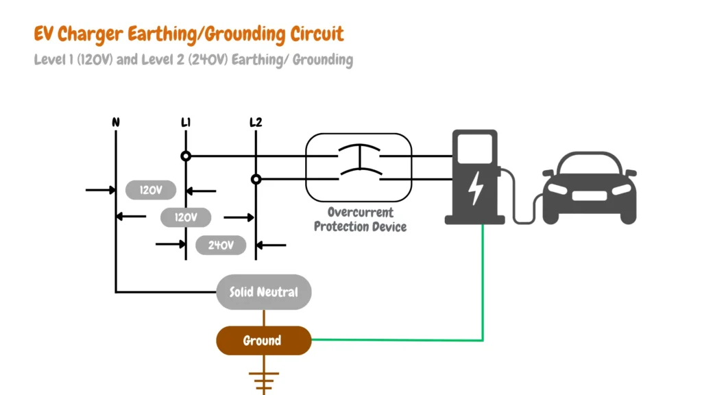
Electric vehicle branch-circuit grounding is typically achieved with a thick copper grounding conductor. This wire connects all exposed metallic parts of the EV charger’s branch circuit to a grounding electrode, such as an earth rod or ground plate buried in moist soil. As shown in the grounding diagrams below, this applies to both 120V/240V split-phase single-phase systems used in North American residential wiring and three-phase EV charger installations used in commercial EV charger installations.
Table of Contents
- Single-Phased EV Charger Circuit Grounding (USA & Canada)
- Three-Phase EV Charger Circuit Grounding
- Does an EV Charger Need to Be Grounded?
- Critical Points Requiring Grounding for EV Chargers
- EV Chargers Grounding/Earthing Components.
- EV Charger Earthing Methods and Types
- Protective Multiple Earth (PME) in EV Charger Installation
- NEC Specifications of Grounding
- Conclusions.
- EV Charger Earthing and Grounding FAQs
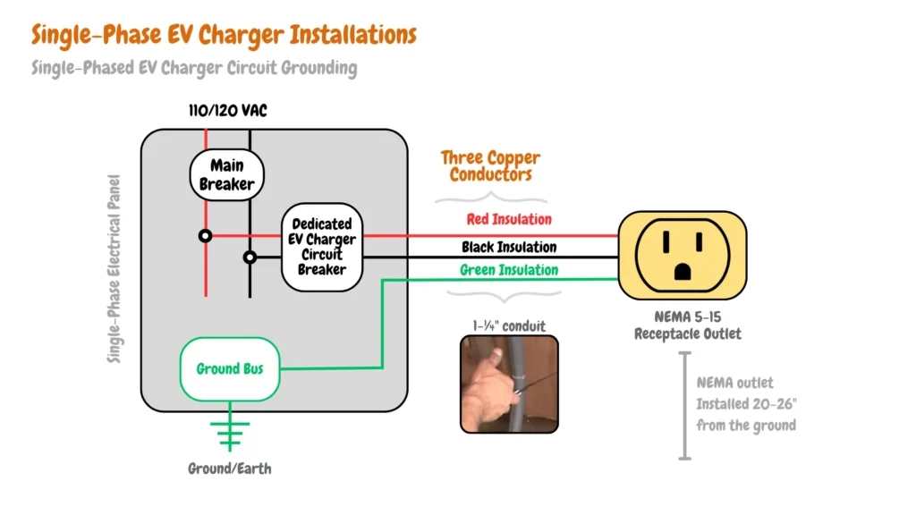
Single-Phased EV Charger Circuit Grounding (USA & Canada)
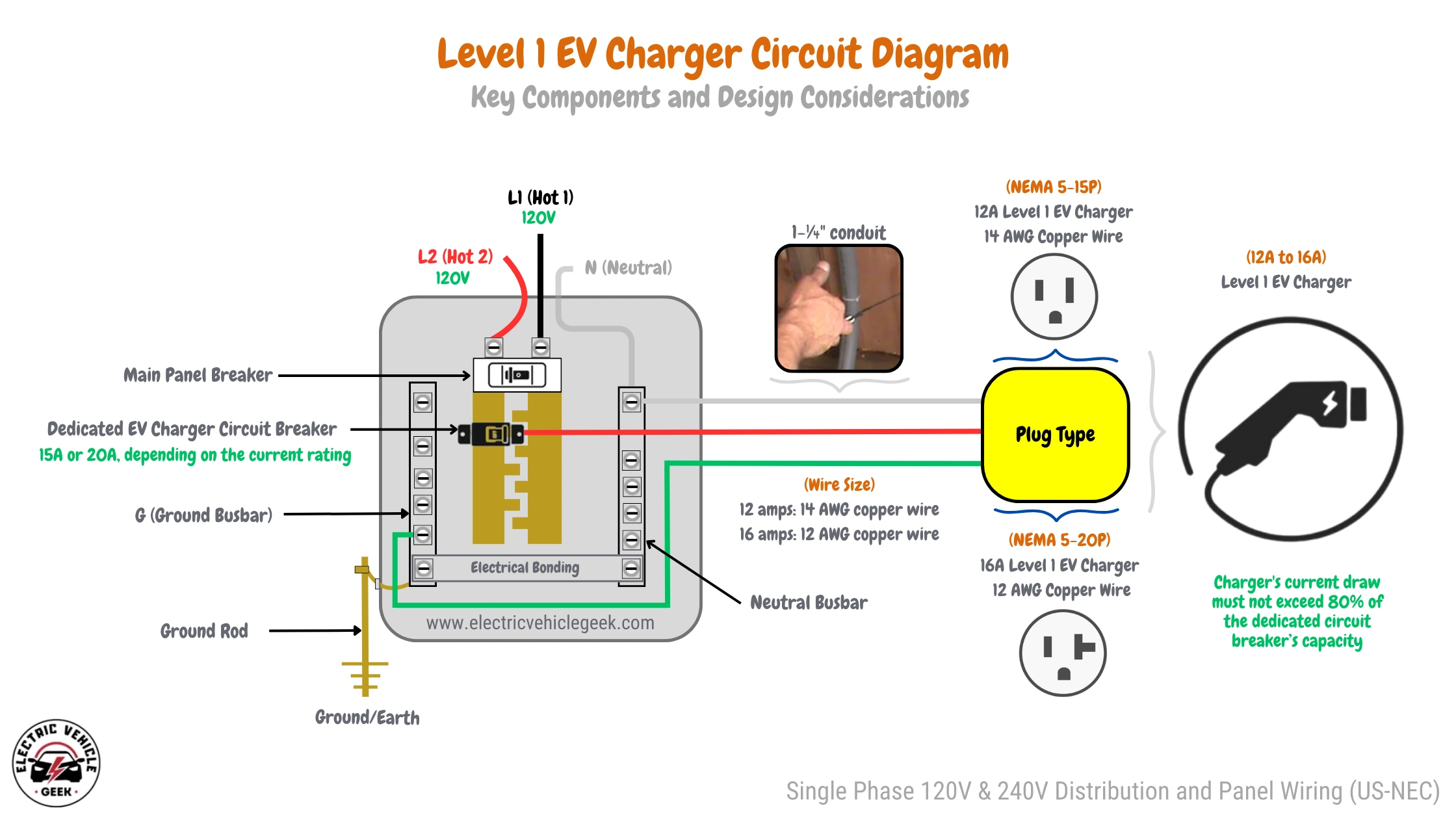
The diagram below demonstrates how a single-phase EV Level 1 charger installation is grounded. It shows the connection between the electrical system and the earth using grounding electrodes and conductors, ensuring a safe and reliable setup.
Level 1 EV Charger Grounding
Level 1 EV chargers utilize a standard NEMA 5-15R or NEMA 5-20 outlet, typically found on a 120-volt circuit. Proper grounding involves connecting the outlet’s grounding conductor to the grounding system of the electrical panel, as shown in the wiring diagrams below:
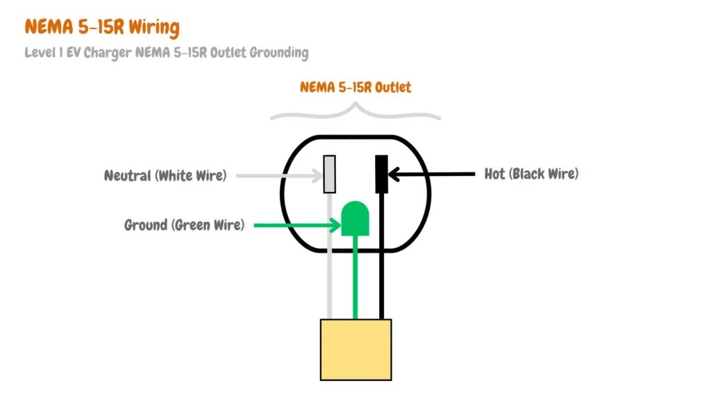
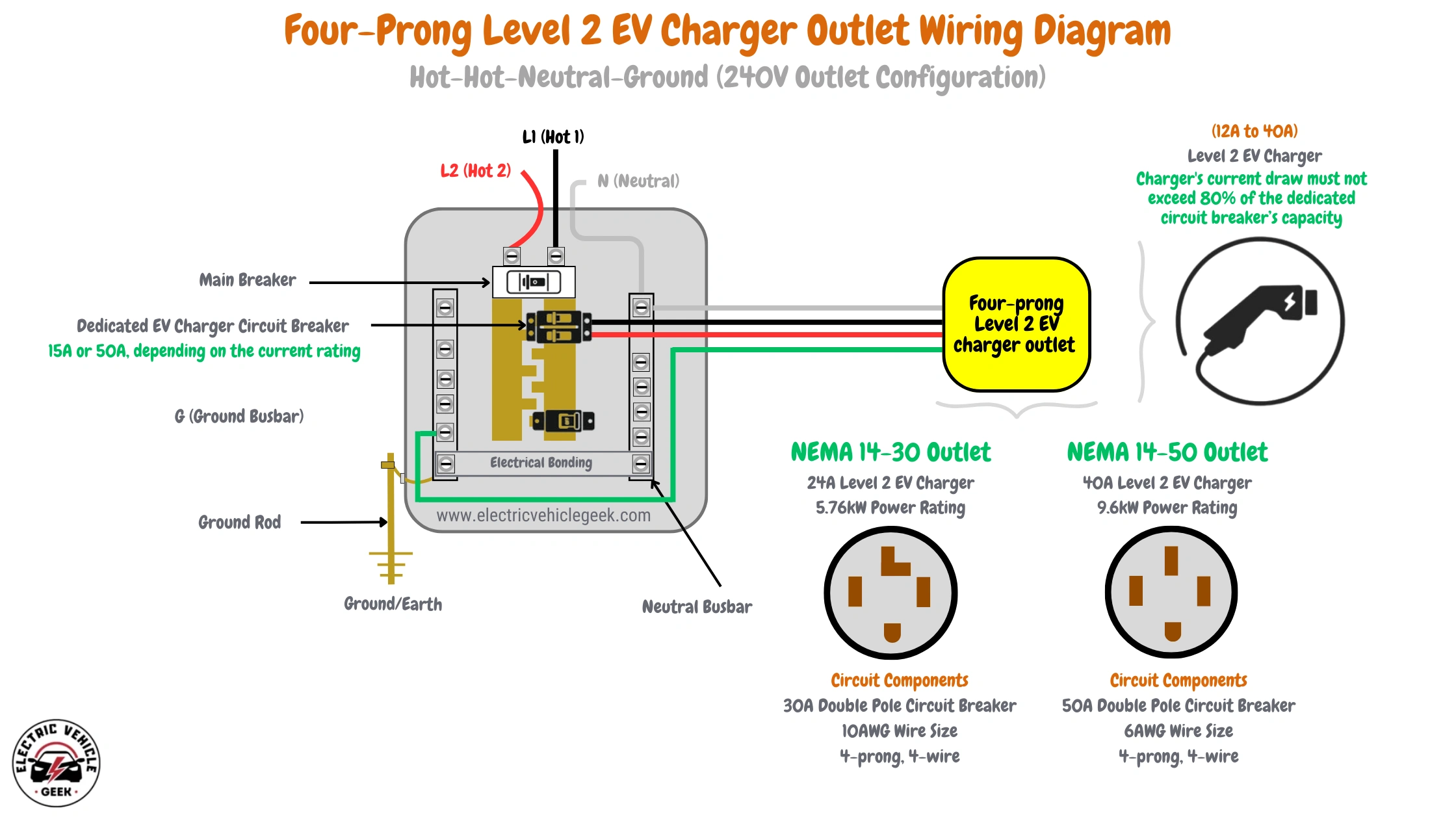
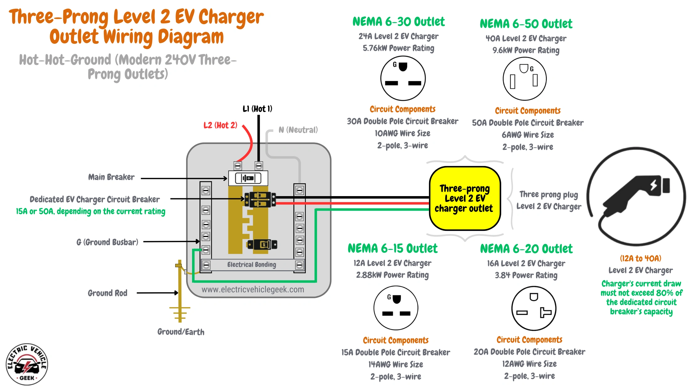
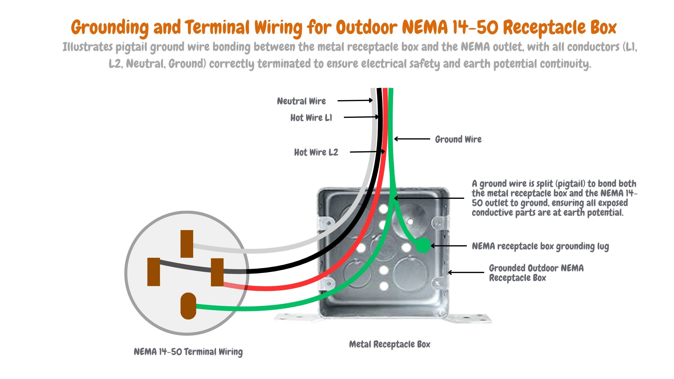
Level 2 EV Charger Outlet Grounding
Level 2 EV chargers commonly use a NEMA 14-50R outlet, which operates on a 240-volt circuit. Proper grounding involves securely connecting the outlet’s grounding terminal to the equipment grounding conductor (EGC), which must be bonded to the main grounding system at the electrical panel.

Three-Phase EV Charger Circuit Grounding
The diagram below illustrates the grounding process for a three-phase Level 2 EV charger. It details the grounding connections required for safely installing three-phase EV chargers, ensuring stability and safety in high-power installations.
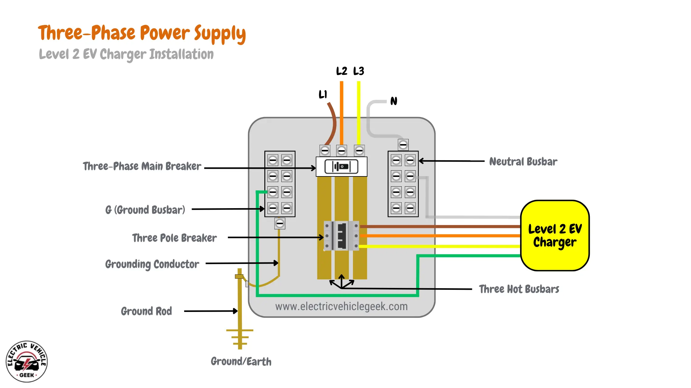
Check out our guide on Three-Phase EV Charger Installation – NEC – US for detailed installation instructions and NEC compliance tips.
Does an EV Charger Need to Be Grounded?
When metallic parts of your electric vehicle’s branch circuit, like outlets and electrical panels, come into contact with a live wire (EV charger leakage fault/ EV charger ground fault) – potentially due to EV charger installation failures or cable insulation breakdown- the metal can become charged. This charge accumulates static electricity. If you touch these charged metallic parts while connecting your EV charger plug or while charging your vehicle, you risk electric shock.
To prevent EV charger leakage and ground faults, the electric vehicle branch circuit must be properly grounded, allowing any electrical charge to dissipate safely into the earth in the event of a fault. However, they are not intended for continuous current flow.
Additional methods for EV charger leakage protection include using devices like ground fault circuit interrupters (GFCIs) or residual current devices (RCDs). These devices monitor current imbalances and automatically cut off power when leakage is detected, effectively preventing electrical hazards.
Critical Points Requiring Grounding for EV Chargers
Before installing an EV charger, it is essential to identify and properly ground all components that could present a safety hazard in the event of a fault. Grounding not only ensures user protection but also guarantees compliance with NEC 250.110 and other applicable standards.
Exposed Metallic Enclosures and Casings
All conductive enclosures and metallic casings associated with the EV charging branch circuit must be bonded to the system grounding path. This includes:
NEMA EV Charger Outlets
For EV chargers using plug-and-socket configurations (e.g., NEMA 5-15R for Level 1 and NEMA 14-50R for Level 2), the grounding pin on both the plug and receptacle must be securely and continuously connected to the grounding system. This connection provides a direct path for any fault current and must be verified during installation and inspection.
For detailed grounding procedures, refer to our NEMA Outlet Installation Guide for practical tips and code-compliant grounding methods.
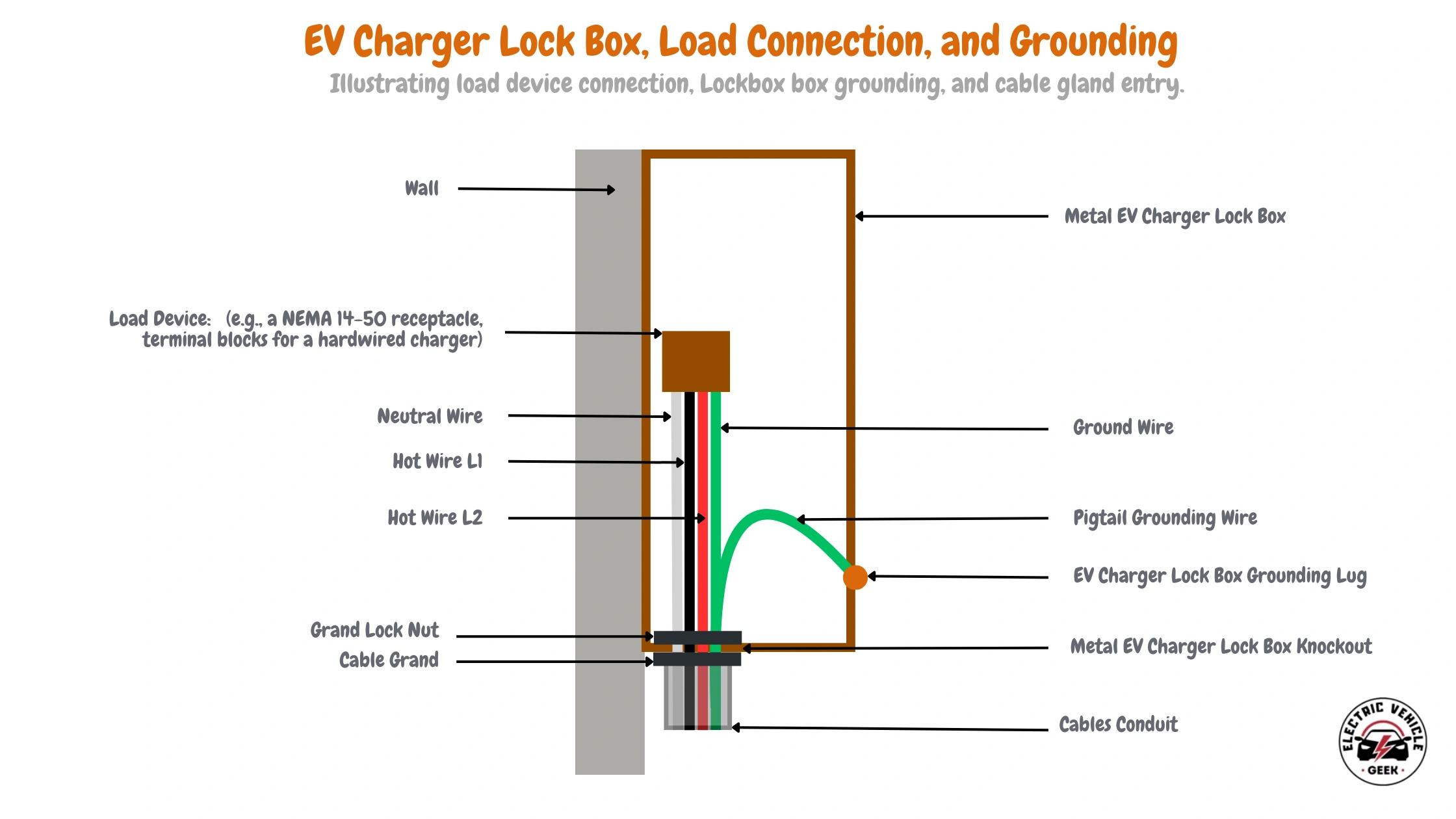
Metal EV Charger Lock Boxes
To ground a metal EV charger lock box, first, install the lock box on the wall and route the hot (L1, L2), neutral, and ground wires to the appropriate terminals on the load device (e.g., NEMA 14-50 receptacle or terminal blocks). Connect the ground wire to the grounding lug inside the box, using a pigtail grounding wire for proper bonding as shown in the diagram below:
Metallic Junction Boxes & Receptacle Boxes
Proper grounding of metallic junction and receptacle boxes is essential for safety in EV charger installations. The ground wire must be securely connected to the grounding terminal inside the box, and the box itself must be bonded to the grounding system using a grounding screw or lug.
For multiple connections, a grounding jumper wire may be required.
Metal Conduits (e.g., EMT, RMC)
Ground metal conduits like EMT and RMC by bonding them to the grounding system using approved connectors at both ends. This provides a path for fault currents to safely reach the ground.
Iron-Clad Switches
Ground iron-clad switches by connecting the grounding wire to the switch’s grounding terminal, ensuring fault currents are safely directed to the ground.
Metal EV Charger Pedestals
Metal EV charger pedestals must be grounded to prevent electric shock and ensure compliance with safety standards. A grounding conductor must be securely bonded to the pedestal’s metal structure and connected to the system’s main earthing point (MET).
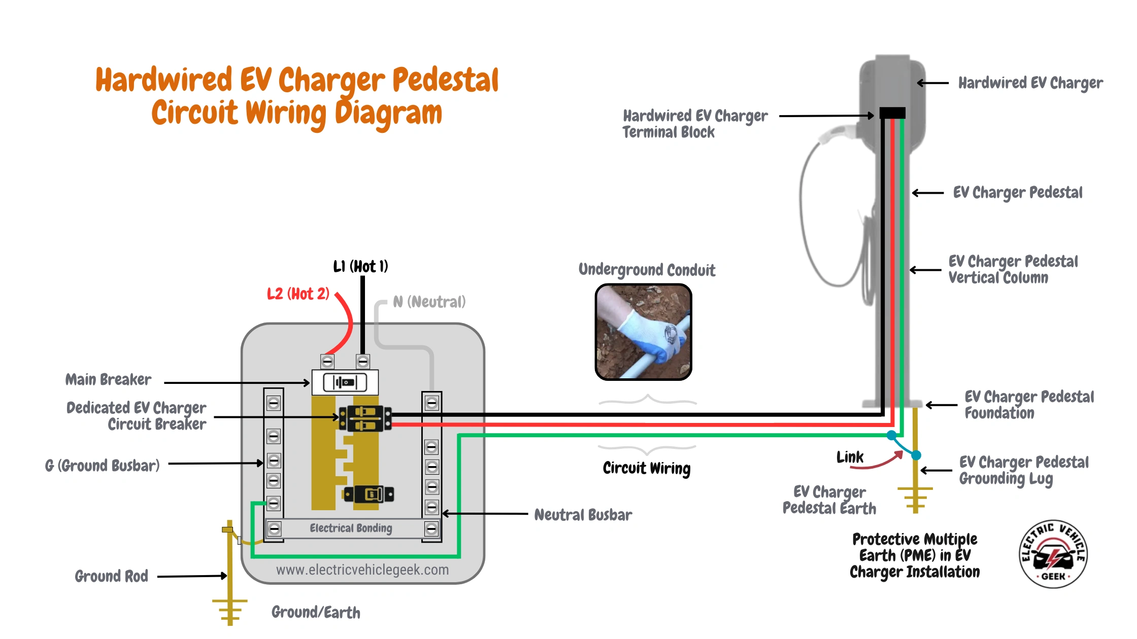
In PME systems, the pedestal’s grounding must also ensure continuity with the PEN conductor to maintain a low-resistance fault path.
EV Charger Pedestal Related Guides
- EV Charger Pedestals 101
- Plug-In EV Charger Pedestal Installation Guide
- Hardwired EV Charger Pedestal Installation Guide
Electrical Distribution Panels
Ground electrical distribution panels by connecting the grounding conductor to the panel’s grounding bus. This directs fault currents safely to earth and ensures compliance with safety standards.
Renewable Energy and Grid-Tied Charger Installations
In hybrid systems using both renewable energy (e.g., solar) and utility power, it is critical to ground all exposed metallic components of the energy system. This includes:
Transformer Frames
To ground transformer frames, connect the grounding conductor to the frame’s grounding lug. This provides a secure path for fault currents to safely flow to Earth, protecting both the equipment and users.
Metallic Inverter Housings
For metallic inverter housings, connect the grounding conductor to the housing’s grounding terminal. This ensures the inverter’s metal parts are properly bonded to the grounding system, safeguarding against electrical shock hazards.
Combiner Boxes and Disconnect Enclosures
In combiner boxes and disconnect enclosures, connect the grounding conductor to the grounding lug or terminal. This step ensures that any fault current is safely directed to the ground, preventing electrical hazards and ensuring system safety.
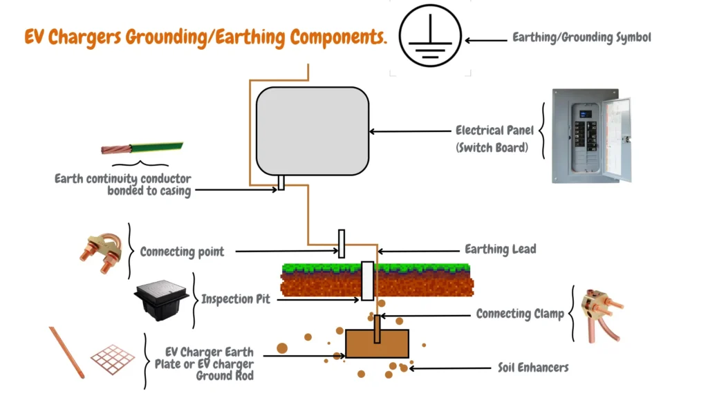
EV Chargers Grounding/Earthing Components.
Components used for grounding/earthing EV charger installations include:
- EV charger electrode conductor.
- EV charger earthing/grounding conductor.
- EV charger earth rod or plate.
The diagram below illustrates the essential grounding components for a safe EV charger installation. It illustrates the electrical path connecting the main service panel to the EV charger’s grounding electrode (earth rod or plate). The diagram also identifies the grounding conductor and any additional electrodes contributing to the grounding system.
EV Charger Electrode Conductor
An EV charger electrode conductor is part of the EV charger grounding system that interconnects all the metallic parts of the electric vehicle branch circuit, such as electrical panels, subpanels, junction boxes, outlets, and the EV charger.
To test the EV charger electrode connecter after EV charger installation, we use the Vici VC480C+ LCD Digital Micro-ohm Meter since the EV charger electrode conductor resistance should be very low to make sure the components of the electric vehicle branch circuit grounding are at the same potential as the ground or earth to prevent the electric vehicle branch circuit from causing an EV charger ground fault in case of insulation faults.
We recommend purchasing the Vici VC480C+ LCD Digital Micro-ohm Meter for frequent monitoring of the resistance or continuity of the branch circuit electrode conductor in your electric vehicle, to maintain and troubleshoot your EV charger installation, especially if you experience ground fault errors displayed on your EV charger.
Your standard digital multimeter can’t measure the resistance or continuity of the electrode conductor on your EV charger. For accurate results, use the Vici VC480C+ LCD Digital Micro-ohm Meter, which ranges from 0.1 µΩ to 2000 Ω. Unlike household multimeters like the AstroAI Multimeter Tester, the VC480C+ meets IEEE standards, ensuring the earth wire’s resistance remains below 1Ω. This compliance is critical for maintaining the safety and functionality of your EV charger installation.
After installation, we recommend keeping a record of the resistance or continuity readings of your EV charger electrode conductor using the Vici VC480C+ LCD Digital Micro-ohm Meter. During maintenance, troubleshooting, or repairs, identify any significant resistance increases that could indicate loose connections or deterioration to prevent shocks.
When EV charger circuit breakers trip due to an EV charger earth leakage fault or ground fault, the culprit can be the EV charger electrode conductor, whose ground fault or leakage current exceeds the set limit. If you have an EV charger with a GFCI circuit breaker, it will trip to prevent potential electrical shock hazards
When choosing the right EV charger grounding cable, the electrode conductor size for the electric vehicle branch circuit will depend on the branch circuit cable/wire size.
Size of EV Charger Electrode Conductor
According to the IEC Regulation, the Earth Continuity Conductor should have a cross-sectional area of at least half of the thickest wire used in the installation, with a minimum of 6 mm². For Level 1 and Level 2 EV chargers, a 6 mm² is recommended.
EV Charger Earthing Lead/Grounding Lead Conductor
The point that connects the EV charger electrode conductor and the EV charger earth plate, EV charger earth pipe, EV charger earth rod, EV charger waterman earthing, or the EV charger strip earthing, depending on your EV charger grounding or earthing method, is known as the EV charger earthing lead/grounding lead conductor
The EV charger earthing lead/grounding lead conductor is the final part of the EV charger earthing system, connecting the EV charger electrode conductor to the underground EV charger earthing system. Depending on your EV charger installation method, your EV charger earthing/grounding Electrode might be an earth plate, earth pipe, earth rod, waterman, or strip earthing.
Not only does the EV charger earthing lead/grounding lead conductor connect the EV charger electrode conductor, and the underground EV charger earthing system, but we also use its connection points to maintain and repair an EV charger earth leakage and faults caused by the EV charger electrode conductor insulation faults, as shown in the illustrative image below:
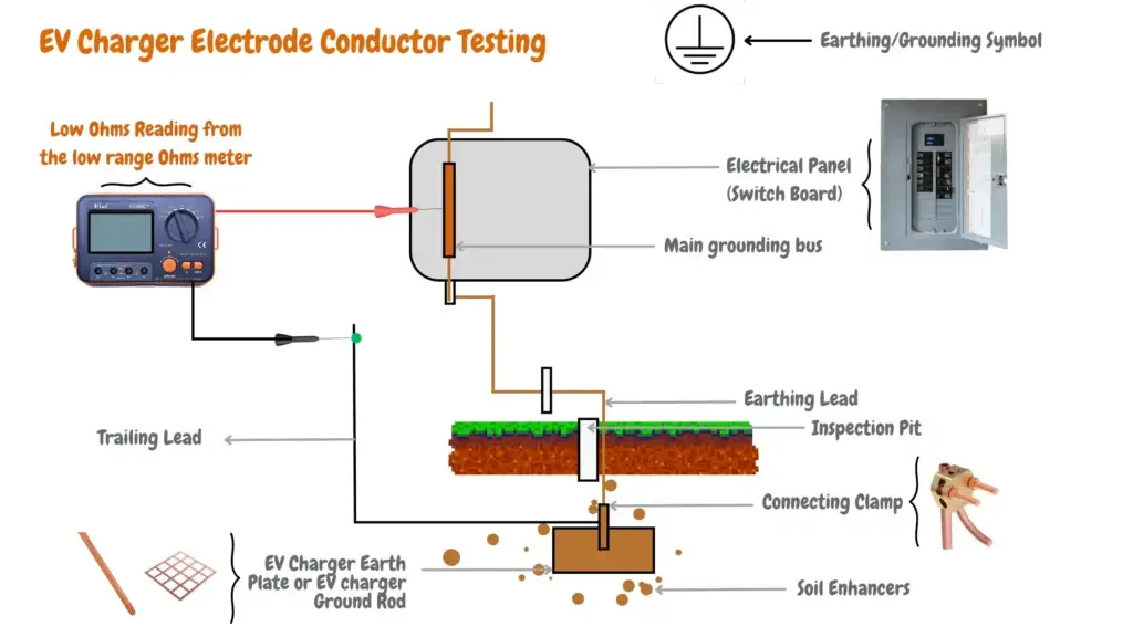
For earth leakage and fault testing with a low-range ohmmeter, we recommend the Vici VC480C+ LCD Digital Micro-ohm Meter. Connect the red probe to the main grounding bus in the EV charger’s electrical panel.
The crucial step is ensuring a good connection on the EV charger earth leads using the black probe. If the lead isn’t directly accessible, a trailing lead (as detailed in our Guide to Testing EV Charger Earth Leakage and Faults) can be employed to reach the grounding point.
As shown in the image above, the EV charger earthing lead/grounding lead conductor should be smaller than the EV charger electrode conductor and installed directly to ground, connected to the EV charger earthing lead/grounding lead conductor.
For EV charger installations such as Level 2 and Level 3 EV chargers, we recommend the use of a copper strip as the EV charger earthing lead/grounding lead conductor, while for Level 1 installations you can use a copper wire, we recommend a copper strip for high current EV charger installations due to their wider ware that can handle high EV charger fault currents compared to the use of a copper wire.
Size of EV Charger Earthing/Grounding Conductor
The size of an EV charger grounding conductor is typically based on the breaker size, as indicated in NEC Table 250.122. This ensures they can handle fault currents without damage.
The table below helps you select the appropriate grounding conductor size for your EV charger installation based on the charger rating (continuous load), the dedicated EV charger circuit breaker size (according to the 20/80 rule), and the conductor material (copper or aluminum).
| EV Charger Rating (Continuous Loads) | EV Charger Dedicated Breaker Size (20/80 Rule) | Grounding Conductor (Copper) | Grounding Conductor (Aluminum) |
|---|---|---|---|
| 12 Amp | 15 Amp | 14 AWG | 12 AWG |
| 16 Amp | 20 Amp | 12 AWG | 10 AWG |
| 20 Amp | 25 Amp | 10 AWG | 8 AWG |
| 24 Amp | 30 Amp | 10 AWG | 8 AWG |
| 28 Amp | 35 Amp | 10 AWG | 8 AWG |
| 32 Amp | 40 Amp | 10 AWG | 8 AWG |
| 36 Amp | 45 Amp | 10 AWG | 8 AWG |
| 40 Amp | 50 Amp | 10 AWG | 8 AWG |
| 48 Amp | 60 Amp | 10 AWG | 8 AWG |
| 56 Amp | 70 Amp | 8 AWG | 6 AWG |
| 64 Amp | 80 Amp | 8 AWG | 6 AWG |
| 72 Amp | 90 Amp | 8 AWG | 6 AWG |
| 80 Amp | 100 Amp | 8 AWG | 6 AWG |
EV Charger Earthing/Grounding Electrode
An EV charger earthing/grounding electrode is the final component of the EV charger earthing or grounding system, although EV charger earth rods and EV charger earth plates are the common EV charger earthing/grounding electrodes other EV charger earthing/grounding electrodes can be used in EV charger installation such as EV charger earth pipe, waterman or strip earthing depending on e.g. soil type, moisture degradation/corrosion of the earth rod over time.
One thing about the EV charger earthing/grounding electrodes no matter what method or type you use on your EV charger installation, we recommend the use of soil enhancers (mixture of charcoal and lime -ratio of 1:3), to improve EV charger earthing/grounding electrode effectiveness in dissipating electrical current into the earth, soil enhancers help lowers soil resistivity, reduced grounding resistance, and help increase the conductivity of the soil including dry, sandy, or rocky soil surrounding the grounding electrode over time.
Size of EV Charger Earthing/Grounding Electrode
When installing an earthing system, using copper as the electrode material is highly recommended due to its superior conductivity and corrosion resistance. A copper electrode should measure 2 feet by 2 feet with a thickness of 1/8 inch (600 mm × 600 mm × 3 mm). It is advisable to bury the electrode in moist soil. If moist soil is unavailable, water can be added to the GI (Galvanized Iron) pipe to create the necessary moisture conditions. To further enhance conductivity, salt and charcoal are added to the earthing pit.
For the EV Charger earth rod, a solid copper rod is recommended. It should be 8 feet (≈2.5 meters) in height and 1/2 inch (12 mm) in diameter. The earth electrode should be installed vertically underground and surrounded by a 1-foot (30 cm) layer of a powdered charcoal and lime mixture in a 1:3 ratio (1 kg of salt to 3 kg of charcoal). This practice helps maintain moisture around the earth’s plate and ensures better continuity in the grounding system.
EV Charger Earthing Methods and Types
There are two common EV charger earthing methods used in installations: an EV charger earth plate or an EV charger earth rod. Although three other EV charger methods exist, such as using an EV charger earth pipe, EV charger waterman, or strip earthing.
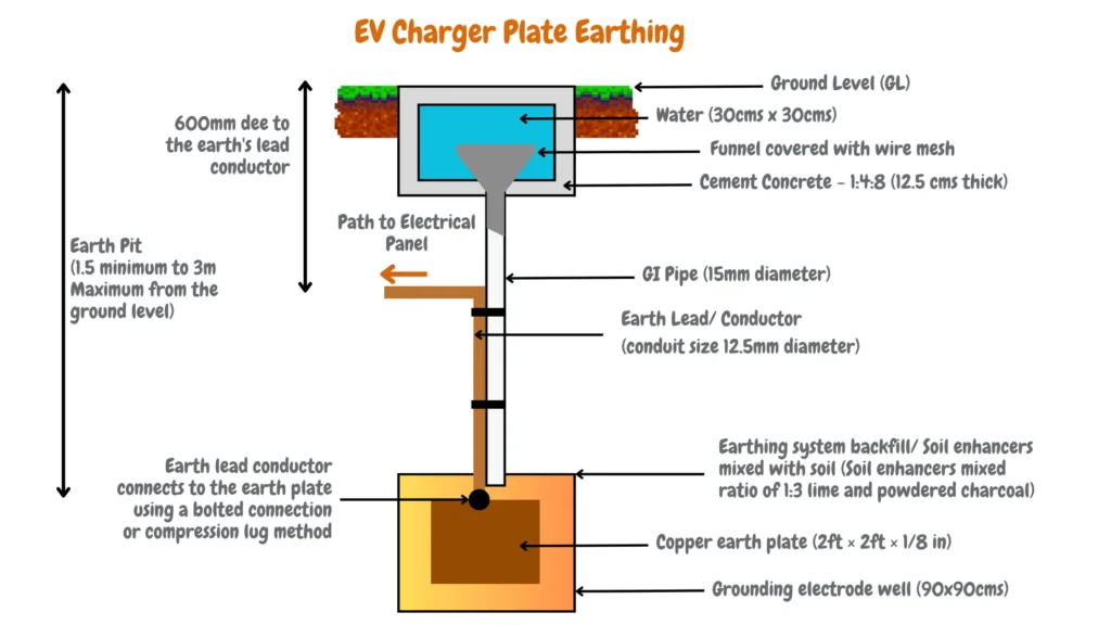
EV Charger Earth Plate
EV charger earth plates are commonly used in permanent, hardwired EV charger installations. These plates are typically installed by EV charger installers at a depth of 1.5 to 3 meters below ground. We generally use a 2 ft × 2 ft × 1/8 in copper earth plate for these installations, as shown in the illustrative image below.
EV Charger Earth Rod
The second most popular EV charging earthing or grounding method is the use of a copper-clad rod EV charger earth rod. EV charger earth rods are common with DIY EV charger installers (which mostly consist of plug-in EV charger installers), but can also be used in hardwired EV charger installations.
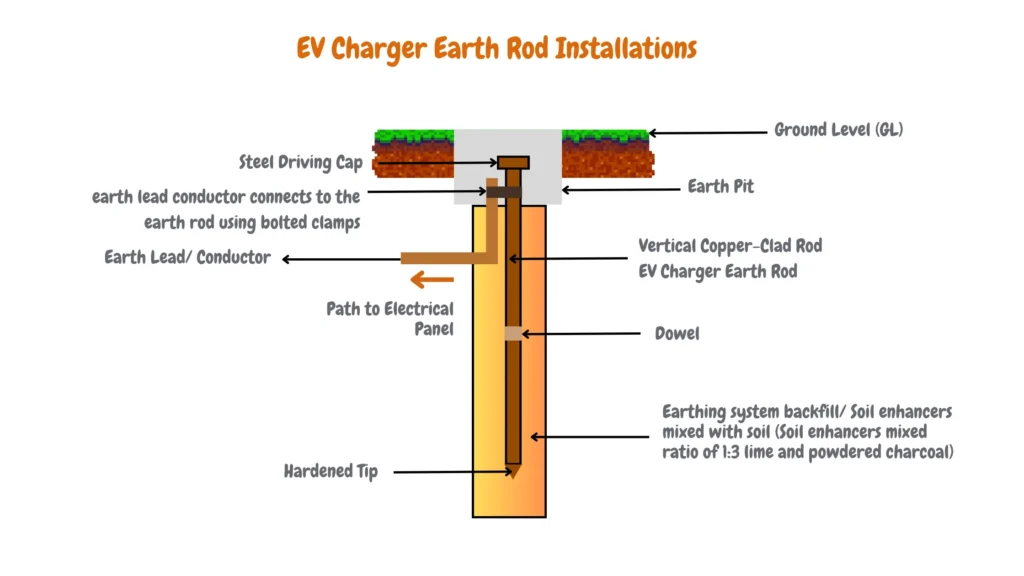
Depending on the soil type and moisture degradation/corrosion of the earth rod over time, the size of the copper-clad rod EV charger earth rod should be a minimum of 3/8in diameter and 4ft in length; however, we recommend 1.5in in diameter and 9ft in length for single home EV charger installation using Level 2 and Level 1 EV chargers. In rocky, dry soils, a larger-diameter copper-clad EV charger earth rod is required.
After installing your EV charger earth rod, use the Vici VC480C+ LCD Digital Micro-ohm Meter to measure the ground resistance or continuity. If it’s greater than 25 ohms, install a supplementary copper-clad EV charger earth rod 6ft apart.
Protective Multiple Earth (PME) in EV Charger Installation
Protective Multiple Earthing (PME) connects the electrical system to ground at multiple points, both at the supply and within the EV charger, providing low-resistance paths to safely divert excess current into the earth.
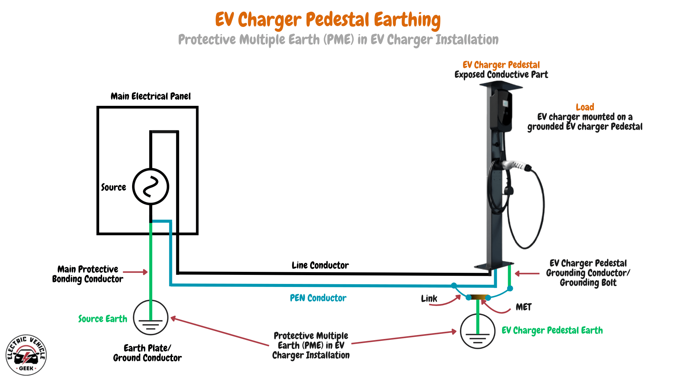
This setup is especially beneficial in the event of an Open-Circuit PEN Conductor fault, where the neutral wire breaks. In such cases, the fault current returns to the supply through parallel paths via the earth, creating a low-resistance circuit.
This allows protective devices, such as fuses or breakers, to trip quickly by allowing high fault currents to flow and cutting off power to prevent shocks, fires, or equipment damage. PME is essential for maintaining safety and reliability in EV charger installations.
NEC Specifications of Grounding
The National Electrical Code (NEC Article 250) outlines various specifications for electrical grounding systems to ensure safety:
- Grounding Electrode System: Every electrical system needs a grounding electrode system, which consists of one or more electrodes, such as rods, plates, or pipes, buried in the earth.
- Minimum Requirements: At least two grounding electrodes are required unless a single electrode achieves resistance to earth below 25 ohms.
- Electrode Installation: Electrodes must be straight down for at least 2.44 meters and be free from non-conductive coatings. Spacing between electrodes from different systems should be at least 1.83 meters.
- Grounding Conductor: A grounding electrode conductor connects the grounding electrode system to the grounded conductor at the service entrance.
- Bonding: The grounded conductor is bonded to the service enclosure and equipment grounding conductors to create a unified grounding path.
- Conductor Sizing: The NEC provides tables specifying the minimum size for grounding and bonding conductors based on system parameters.
Conclusions.
Grounding EV chargers is crucial for safety, compliance, and functionality. This guide covers key aspects of EV charger grounding, emphasizing compliance with the National Electrical Code (NEC).
- Circuit Grounding: Single-phased and three-phased EV chargers require different grounding approaches. Proper grounding ensures safety and stability.
- NEMA Outlets: Grounding for Level 1 (NEMA 5-15R) and Level 2 (NEMA 14-50R) chargers involves specific practices to meet NEC requirements and prevent electric shocks.
- Critical Grounding Points: Properly grounding the charger, circuit, and components is essential to provide a safe path for fault current and protect the system.
- Components and Conductor Sizing: Properly sized grounding components and conductors ensure effective fault-current dissipation. This includes the electrode conductor, earthing lead, and grounding electrode.
- Earthing Methods: Different methods, such as earth rods and plates, offer distinct advantages. Proper installation ensures effective grounding and reduces the risk of electric shock.
- NEC Compliance: Following NEC guidelines is critical for the legal and safe operation of EV chargers. These standards protect users and equipment.
Effective EV charger grounding involves understanding charger types, installation environments, and regulatory standards. Proper grounding protects users and equipment and ensures long-term functionality and reliability.
EV Charger Earthing and Grounding FAQs
These FAQs answer the most common questions about EV charger earthing and grounding in the United States. Each answer complies with the National Electrical Code (NEC)
What is EV charger earthing, and why does it matter?
EV charger earthing, also called grounding, is the wire path that connects the metal parts of your EV charger’s circuit to ground. It provides a safe path for stray current to flow during a fault. Without grounding, the metal body of your charger or car could become live. Anyone touching it could get a serious electric shock. Proper grounding is the first line of safety in every EV charger install.
Can I charge my EV without a ground connection?
No. Almost every modern EV charger checks for a good ground before sending power to the car. If the ground is missing or weak, the charger will lock out and refuse to start the session. This safety check is built into the charger by design. It protects you, the car, and the building wiring from shock and fire risk. Learn more in our EV charger safety guidelines.
Is grounding an EV charger different from grounding a regular home appliance?
Yes. EVs sit outside in the rain, snow, and heat. They also have a large metal body that a person can touch while charging. That mix of moisture and human contact increases the risk of shock. Because of this, NEC 625 and Article 250 set tighter rules for EV charger circuits. These rules cover dedicated breakers, GFCI protection, and a strong ground path back to the main panel.
What are the dangers of poor EV charger grounding?
A bad ground can lead to electric shock, damage to the car battery system, and even electrical fires. Stray voltage can sit on the car body without warning until someone touches it. Poor grounding also stops safety devices like GFCI breakers from tripping in time. That delay can turn a small fault into a major event.
Do I always need to install a ground rod for an EV charger?
Not always. In most US homes, the EV charger is connected to the existing grounding system at the main service panel. That system already includes ground rods or a grounding electrode buried during the home build. Some outdoor pedestal installs and many commercial sites do need a fresh ground rod near the charger. Your installer will check soil resistance and local code before deciding.
How deep should an EV charger ground rod be?
The NEC requires the ground rod to sit at least 8 feet into the earth. Most installers use an 8-foot-long, half-inch-thick copper-clad rod. The rod must reach moist soil for a low resistance reading. On dry or rocky ground, you may need a longer rod, a second rod 6 feet away, or soil enhancers like a charcoal-and-salt mix.
What size grounding wire do I need for my EV charger?
The wire size depends on the breaker size for your charger circuit. NEC Table 250.122 sets the minimum. For a 40-amp charger on a 50-amp breaker, you need 10 AWG copper. For an 80-amp charger on a 100-amp breaker, you need 8 AWG copper. Always match the grounding conductor to the breaker, not the charger amps. This keeps the wire safe even during a full fault current.
Can my Level 2 EV charger share the home grounding system?
Yes. A hardwired Level 2 charger or a NEMA 14 50 outlet ties into the same grounding bus inside your main panel. The panel ground bonds to the main ground rod and water pipe per NEC 250. The key is a solid, continuous ground wire from the charger back to that main bus. No splices, no rust, no loose lugs.
What is a ground fault on an EV charger?
A ground fault occurs when current leaks from a hot wire onto a metal surface or into the ground. It often comes from worn insulation, water in the plug, or a damaged charging cable. Modern EV chargers include a built-in CCID or GFCI sensor. The sensor watches for tiny current leaks and shuts the charger off in milliseconds when it sees one.
Why does my EV charger show a ground fault error?
Stop charging when this error shows up. The most common causes are water in the plug, a corroded ground rod, a loose ground screw in the outlet, or a damaged charging cable. Our guide to testing EV charger earth leakage and faults walks through each check. Try a different outlet first to rule out the cable. If the error returns, call a licensed electrician to test the ground path with a meter before you charge again.
Why is the NEMA 14 50 outlet so common for EV charging?
The NEMA 14 50 is a 240-volt, 50-amp outlet with two hots, a neutral, and a ground. It supports most Level 2 chargers up to 40 amps of output and is already used in RV parks and kitchens. Its four-prong design provides a clean ground path that meets NEC requirements. That is why it became the default plug for home EV charging in the US.
What does the NEC say about EV charger grounding?
NEC Article 625 covers EV charging equipment, and Article 250 covers grounding and bonding. Together, they require a dedicated circuit, a sized grounding conductor, GFCI protection on outdoor outlets, and a bonded path back to the service panel. The 2023 NEC also mandated surge protection for EV circuits and clearer labeling. Local amendments may add more rules, so check with your city before installing.
Do commercial EV charging stations need a separate grounding system?
Often yes. Commercial chargers handle higher loads and longer runs, so they may use their own ground rod array, a buried copper grounding mat, or a ground ring around the pedestal. See our three-phase EV charger installation guide for full layouts. This setup maintains a uniform ground potential across the entire charging area. It also protects users when many cars are charging simultaneously.
What is the difference between bonding and grounding in an EV charger circuit?
Grounding sends fault current to the earth. Bonding ties all metal parts together so they sit at the same voltage. Both work as a team. In your EV charger install, the conduit, outlet box, charger case, and pedestal are all bonded with green or bare copper wire. That bonded path then connects to the ground rod through the main panel.
Does soil moisture affect EV charger grounding?
Yes, a lot. Wet soil carries current well, while dry sand or rock fights it. A dry ground rod can read 100 ohms or more, far above the 25 ohm limit set by NEC 250.53. In dry climates, installers add longer rods, a second rod, or backfill the pit with a charcoal-lime mix. These steps pull moisture in and keep resistance low year-round.
How often should I test the ground on my EV charger?
Have a licensed electrician test the ground loop at least once a year. They will measure resistance with a clamp meter or a micro-ohm meter and check each lug for tightness. Also, test after any storm, flood, or major yard work near the rod. Ground rods can shift, corrode, or break without any sign on the surface.
Do DC fast chargers need different grounding than AC home chargers?
Yes. DC fast chargers push much higher current and create more leakage at high frequency. They use heavier ground cables, dedicated ground grids, and isolation monitors that monitor the ground path in real time. Home-level 1 and 2 chargers use simpler grounding because their amperage and voltage are much lower. The basic NEC rules cover them well.
What is a ground loop, and how does it cause EV charger problems?
A ground loop forms when ground current flows in a circle between two grounding points at slightly different voltages. It can cause buzzing, false GFCI trips, and worn-down equipment over time. In EV charger circuits, ground loops often show up when a subpanel has its own rod that is not bonded directly to the main panel. A licensed electrician can quickly find and fix the loop.
Can a portable Level 1 EV charger work on any outlet?
Only on a properly grounded three-prong NEMA 5 15 or NEMA 5 20 outlet. The Level 1 charger checks for ground before it starts. Older two-prong outlets and most cheater adapters will fail this check. Never use a two-prong adapter to bypass the ground pin. It removes your shock protection and can damage the car’s charging system.
What is a copper grounding mat, and when should I use one?
A grounding mat is a flat copper mesh that is buried beneath the concrete pad of a charging station. It keeps the ground voltage even across the whole pad, even during a heavy fault. Mats are common at commercial sites, fleet depots, and DC fast charger pads. They cost more than a single rod but give the best safety for crowded charging zones.

James Ndungu is a certified EV charger installer with over five years of experience in EVSE selection, permitting, and installation. He holds advanced credentials, including certification from the Electric Vehicle Infrastructure Training Program (EVITP) and specialized training in EV charging equipment and installation, as well as diplomas in EV Technology and Engineering Fundamentals of EVs. Since 2021, James has tested dozens of EV chargers and accessories, sharing expert insights into the latest EV charging technologies.
Last update on 2026-07-20 / Affiliate links / Images from Amazon Product Advertising API