EV charger Voltage drop occurs when electrical current travels through cables, causing a loss in voltage. Excessive voltage drop can reduce charger efficiency, increase charging time, and strain the electrical system.
This guide explains voltage drop in EV charger circuits, identifies key points where it can occur, and helps installers and electricians prevent voltage drops in EV charger installations.
Table of Contents
- What Causes Voltage Drop in EV Charger Circuits?
- Circuit Wire Length and Thickness
- EV Charger Circuit Load and Its Impact on Voltage Drop
- Circuit Connections and Components
- EV Charger Extension Cords
- EV Charging Adapters
- Voltage Drop in Hardwired EV Charger Circuits
- Voltage Drop in Plug-in EV Chargers
- Voltage Drop When Using Extension Cords
- Voltage Drop When Using NEMA Outlet Conversion Adapter
- How to Check Voltage Drop in EV Charger Circuits
- Example 1: Level 1 EV Charger (120V, 15A Circuit)
- Specs:
- Voltage Drop Calculation:
- Result:
- Example 2: Level 2 EV Charger (240V, 40A Circuit)
- Specs:
- Voltage Drop Calculation:
- Result:
- Example 3: Level 2 EV Charger (Voltage Drop Too High)
- Voltage Drop Calculation:
- Result:
- Editor’s Tip: Use the Fluke FEV150 Analyzer for Fast, Accurate Voltage Drop Testing
- Final Thoughts
What Causes Voltage Drop in EV Charger Circuits?
Voltage drop in EV charger circuits is caused by electrical resistance in the wires, which increases with longer distances, thinner wire gauges, and certain wire types. Longer cable runs, especially outdoors or underground, increase resistance and reduce charging efficiency. Thinner wires (higher AWG) and materials like aluminum have more resistance than thicker copper wires. Using properly sized, low-resistance copper wire helps minimize voltage drop and ensures safe, efficient EV charging.
For EV charger installations, we recommend using copper conductors. Copper has lower resistance than aluminum, making it a better choice for maintaining stable voltage levels in EV charger installations. Although aluminum wiring may appear in voltage drop charts, EV charger and accessories manuals, or online forums, we do not recommend it for EV charger installations.
Circuit Wire Length and Thickness
The longer the wire, the higher its resistance, leading to increased voltage drop. Similarly, thinner wires have more resistance than thicker ones, resulting in greater power loss and potential overheating.
Choosing the right wire gauge for EV charger installation ensures efficient power delivery and reduces the risk of electrical hazards.
What is the Maximum Length of an EV Cable?
According to the National Electrical Code (NEC), the recommended maximum voltage drop for dedicated EV charger branch circuits is 3%. Keeping voltage drop within this limit ensures efficient charging and prevents potential electrical issues.
Maximum Cable Lengths for EV Chargers
Based on our testing and calculations, we created the following tables to help installers and electricians size EV installation cables correctly. This guide uses circuit voltage, wire size (AWG), and the NEC’s 3% voltage drop recommendation to determine maximum cable lengths for both Level 1 and Level 2 EV chargers.
120V EV Chargers (Level 1 EV Charger) Circuit Conductors Sizing
| Wire Gauge | Length |
|---|---|
| 14 AWG | 50 Feet |
| 12 AWG | 60 Feet |
| 10 AWG | 64 Feet |
| 8 AWG | 76 Feet |
| 6 AWG | 94 Feet |
240V EV Chargers (Level 2 EV Charger) Circuits Conductors Sizing
| Wire Gauge | Length |
|---|---|
| 14 AWG | 100 Feet |
| 12 AWG | 120 Feet |
| 10 AWG | 128 Feet |
| 8 AWG | 152 Feet |
| 6 AWG | 188 Feet |
Voltage Drop Guide for Level 1 EV Charger Wiring (120V Circuit)
This table helps you understand how wire length and gauge impact voltage drop in Level 1 EV chargers. Longer and thinner copper wires increase resistance, leading to power loss and potential overheating.
| Charger Amps (A) | Circuit Length (ft) | Min. Wire Size (AWG) | Approx. Voltage Drop (V) | Approx. Voltage Drop (%) |
|---|---|---|---|---|
| 12 | 25 ft | 14 | 1.51V | 1.3% |
| 12 | 50 ft | 14 | 3.03V | 2.5% |
| 16 | 25 ft | 12 | 1.27V | 1.1% |
| 16 | 50 ft | 12 | 2.54V | 2.1% |
Voltage Drop Guide for Level 2 EV Charger Wiring (240V Circuit)
Voltage drop increases with wire length and smaller gauge sizes, affecting charging efficiency and safety. Use this table to determine the appropriate copper wire gauge and length for Level 2 EV chargers based on circuit distance and current draw.
| Charger Amps (A) | Circuit Length (ft) | Min. Wire Size (AWG) | Approx. Voltage Drop (V) | Approx. Voltage Drop (%) |
|---|---|---|---|---|
| 12A | 25 ft | 14 AWG | 1.51V | 0.6% |
| 12A | 50 ft | 14 AWG | 3.03V | 1.3% |
| 16A | 25 ft | 12 AWG | 1.27V | 0.5% |
| 16A | 50 ft | 12 AWG | 2.54V | 1.1% |
| 20A | 25 ft | 10 AWG | 1.00V | 0.4% |
| 20A | 50 ft | 10 AWG | 2.00V | 0.8% |
| 24A | 25 ft | 10 AWG | 1.20V | 0.5% |
| 24A | 50 ft | 10 AWG | 2.40V | 1.0% |
| 28A | 25 ft | 8 AWG | 0.88V | 0.4% |
| 28A | 50 ft | 8 AWG | 1.76V | 0.7% |
| 32A | 25 ft | 8 AWG | 1.00V | 0.4% |
| 32A | 50 ft | 8 AWG | 2.01V | 0.8% |
| 36A | 25 ft | 6 AWG | 0.71V | 0.3% |
| 36A | 50 ft | 6 AWG | 1.42V | 0.6% |
| 40A | 25 ft | 6 AWG | 0.79V | 0.3% |
| 40A | 50 ft | 6 AWG | 1.58V | 0.7% |
| 48A | 25 ft | 4 AWG | 0.60V | 0.2% |
| 48A | 50 ft | 4 AWG | 1.19V | 0.5% |
| 56A | 25 ft | 4 AWG | 0.70V | 0.3% |
| 56A | 50 ft | 4 AWG | 1.39V | 0.6% |
| 64A | 25 ft | 3 AWG | 0.63V | 0.3% |
| 64A | 50 ft | 3 AWG | 1.26V | 0.5% |
| 72A | 25 ft | 2 AWG | 0.56V | 0.2% |
| 72A | 50 ft | 2 AWG | 1.13V | 0.5% |
| 80A | 25 ft | 2 AWG | 0.63V | 0.3% |
| 80A | 50 ft | 2 AWG | 1.25V | 0.5% |
EV Charger Circuit Load and Its Impact on Voltage Drop
Voltage drop increases as the electrical load on a circuit rises. Overloading a circuit is not only unsafe but also inefficient, significantly worsening the voltage drop. Exceeding the recommended 80% of a circuit’s rated capacity introduces excessive resistance, resulting in greater energy loss and potential equipment stress.
Higher amperage draws more current, which in turn increases the amount of voltage lost across the wiring. For example, a 16-amp EV charger will cause more voltage drop than a 12-amp EV charger on identical wiring. This loss shows up as heat, reducing charging efficiency and increasing the risk of overheating.
To maintain safe and efficient operation, we recommend keeping the total continuous load on any EV charger circuit at or below 80% of the circuit breaker’s rating. This practice is mandated by the National Electrical Code (NEC) 210.20(A), which requires that the overcurrent protective device be rated for at least 125% of the continuous load.
For detailed guidance on selecting the right circuit breaker size for your EV charger, including ampacity charts and real-world examples, refer to our EV Charger Circuit Breaker Selection Guide.
Circuit Connections and Components
Loose or corroded electrical connections, worn-out outlets, and weak circuit breakers add resistance, causing voltage loss. A loose plug in a standard 120V outlet can reduce charging efficiency and even create a fire hazard. Regularly inspecting and maintaining your electric vehicle’s branch circuit connections ensures safe and consistent EV charging performance.
EV Charger Extension Cords
Using an undersized or low-quality extension cord significantly increases resistance, resulting in voltage drop and potential overheating. For example, a 16 AWG extension cord can struggle to deliver power efficiently, reducing charging speed for Level 1 chargers like the Lectron Level 1 EV Charger. In contrast, a properly rated 12 AWG extension cord ensures stable power delivery for Level 1 chargers.
EV Charging Adapters
Using an EV charging adapter may cause a voltage drop, which lowers the power delivered to your vehicle. This effect results from resistance in wires and connectors. Longer cables, thin wires, low-quality adapters, and loose connections worsen the issue by slowing charging, creating heat, and increasing the risk of power loss and equipment damage.
EV charger adapters, such as J1772-to-NACS adapters, can contribute to voltage drop by introducing additional resistance along the electrical path. Resistance from connectors, cables, and adapter contacts can lower the voltage delivered to the vehicle. Increased adapter complexity, poor material quality, and loose connections all exacerbate voltage drop, reducing charging efficiency and safety.
Voltage Drop in Hardwired EV Charger Circuits
Hardwired EV chargers connect directly to the electrical panel using a dedicated circuit in a hardwired EV charger installation.
Common Voltage Drop Points
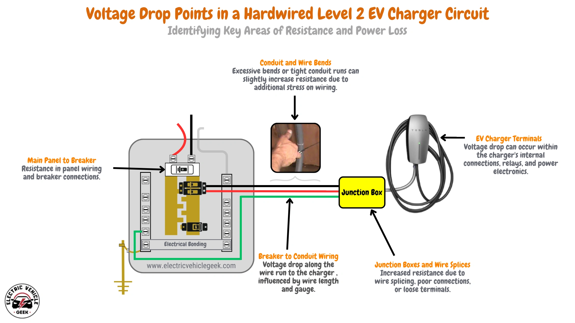
- Main Service Panel to Breaker: Resistance in the panel wiring, breaker contacts, and bus bar connections.
- Breaker to Conduit Wiring: Voltage drop along the wire run to the charger, influenced by wire length and gauge. Check out our guide on EV charger installation conduits.
- Junction Boxes and Wire Splices: Increased resistance due to wire splicing, poor connections, or loose terminals.
- EV Charger Disconnect Switch (if applicable): Some installations, such as solar EV charging, include a disconnect switch, which can introduce resistance at its terminals.
- Conduit and Wire Bends: Excessive bends or tight conduit runs can slightly increase resistance due to additional stress on wiring.
- EV Charger Internal Wiring: Voltage drop can occur within the charger’s internal connections, relays, and power electronics.
- Vehicle Charging Port and Connector: Contact resistance at the charging plug and vehicle inlet can cause minor voltage drops, especially if there’s corrosion or wear.
Solutions
Now that you understand the key areas of resistance in a hardwired EV charger installation, let’s explore some solutions to minimize voltage drop.
- Use Proper Wire Gauge: To minimize resistance, select a thicker wire (lower AWG) based on circuit length and current rating.
- Minimize Wire Length: Shorter runs reduce resistance and voltage drop. Keep the charger as close as possible to the panel.
- Ensure Secure Connections: Tighten all terminals and use high-quality connectors to reduce contact resistance.
- Upgrade Panel and Breakers: Use properly rated breakers and ensure good connections at the bus bars.
- Limit Junction Boxes and Splices: Reduce the number of splices and use high-quality, properly crimped or soldered connections.
- Use a Dedicated Circuit: Avoid shared circuits that could introduce additional voltage drop due to extra load.
- Check and Maintain Charging Connectors: Inspect the EVSE plug and vehicle inlet for wear, corrosion, or dirt buildup.
- Optimize Conduit Runs: Avoid excessive bends and tightly packed wires in conduits, which can slightly increase resistance.
By addressing these areas, you can ensure efficient power delivery, reduce heat buildup, and maximize the performance of your Level 2 EV charger.
Voltage Drop in Plug-in EV Chargers
Plug-in EV chargers rely on NEMA outlets such as NEMA 14-50, NEMA 6-50, or NEMA 5-15 for power delivery. Voltage drop can occur at multiple points in the circuit, leading to reduced charging efficiency and potential overheating.
Common Voltage Drop Points and Solutions
Below are the most common problem areas and how to address them.
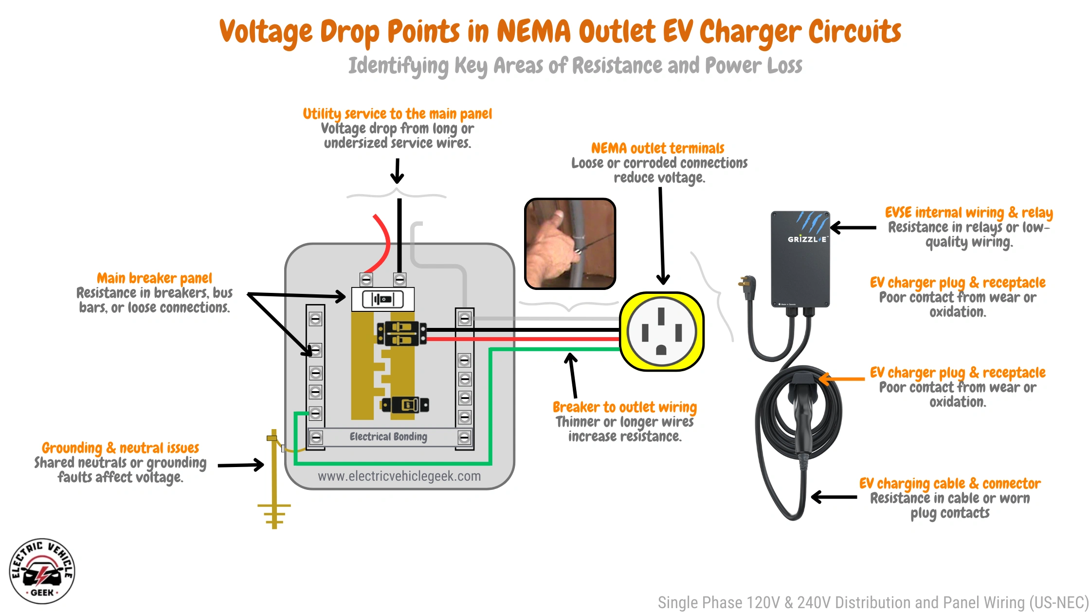
Utility Service to the Main Panel
Issue: Long or undersized service wires cause voltage loss before reaching your home panel.
Solution:
- Upgrade to a larger gauge service wire if the run is long.
- Ensure service wire meets NEC ampacity requirements to handle the EV charger’s load.
- Work with a qualified electrician for professional assessment and installation.
Main Breaker Panel
Issue: Resistance in breakers, bus bars, or loose connections can cause voltage fluctuations.
Solution:
- Tighten all electrical connections to the manufacturer’s torque specifications.
- Use an anti-oxidation compound on aluminum conductors.
- Periodically inspect and replace corroded or damaged breakers to prevent overheating.
Breaker to Outlet Wiring
Issue: Long or undersized wires between the breaker and outlet increase resistance.
Solution:
- Use the correct wire gauge based on circuit requirements (e.g., #10 AWG for 30A, #8 AWG for 40A+).
- Minimize wire length and avoid unnecessary splices that can add resistance.
Check out our guide on installing NEMA outlets for EV charging.
NEMA Outlet Terminals
Issue: Loose or corroded outlet terminals lead to voltage loss and overheating.
Solution:
- Ensure all terminal screws are properly tightened.
- Use industrial-grade NEMA outlets designed for frequent high-power use.
- Apply dielectric grease to prevent oxidation and improve electrical conductivity.
EV Charger Plug & Receptacle
Issue: Poor contact from wear, oxidation, or loose connections reduces charging efficiency.
Solution:
- Regularly inspect and clean plug contacts.
- Replace worn or loose receptacles with high-quality NEMA-rated outlets.
- Use dedicated EVSE outlets rated for frequent plugging and unplugging.
EVSE Internal Wiring & Relay
Issue: Resistance in internal relays or low-quality wiring affects power delivery.
Solution:
- Invest in high-quality plug-in EV chargers from reputable brands with UL-listed components. Check out our curated list of the most reliable plug-in EV chargers we recommend.
- Regularly inspect the relay contacts for signs of wear or pitting.
EV Charging Cable & Connector
Issue: Resistance in charging cables and worn plug contacts limits power flow.
Solution:
- Use shorter, heavy-duty cables with sufficient ampacity.
- Replace frayed or damaged cables immediately.
- Keep connectors clean and dry to prevent corrosion.
Choosing the right EV charging cable ensures safe, efficient charging. Check out our EV charging cable guide to find the best option for your needs.
EV Charging Circuit Grounding & Neutral Issues
Issue: Shared neutrals or improper grounding can cause voltage fluctuations and safety hazards.
Solution:
- Ensure a dedicated neutral and ground connection per NEC regulations.
- Verify proper bonding at the main service panel.
- Install ground rods if necessary to improve grounding quality.
- Inspect for loose neutral connections in breaker panels and outlets. Check out our guide on wiring a main circuit breaker panel for EV charging.
Voltage Drop When Using Extension Cords
Many EV owners use extension cords for Level 1 chargers because standard charging cables may not reach the nearest outlet, some homes lack dedicated EV outlets, or they need a temporary charging solution.
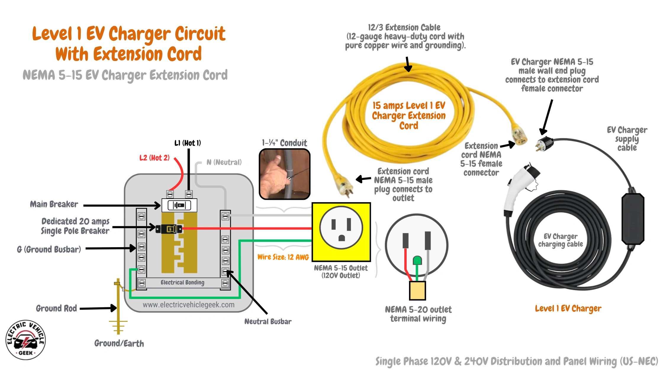
However, this can lead to a voltage drop due to increased electrical resistance. The main causes of voltage drop include:
- Cord Length and Thickness: Longer or thinner cords increase resistance.
- Plug Connections: Loose or poor-quality plugs reduce efficiency.
- Multiple Cord Connections: Using more than one extension cord increases voltage drop significantly.
Solution: Use a high-quality, insulated extension cord that is short and thick. For a 120V Level 1 charger, choose a 12 AWG copper-wired extension cord. Avoid daisy-chaining multiple cords.
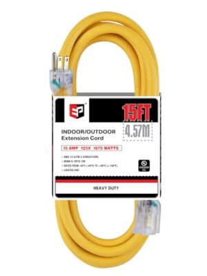
Recommended Level 1 EV Charger Extension Cords
For safe and efficient charging, choose a premium 12 AWG copper-wired extension cord designed to handle the continuous load of Level 1 EV charging. These cords minimize voltage drop, prevent overheating, and ensure reliable performance.
Below are our top-rated Level 1 EV charger extension cord recommendations, offering the best combination of safety and durability.
Voltage Drop When Using NEMA Outlet Conversion Adapter
A NEMA outlet conversion adapter allows an electric vehicle charger to connect to different NEMA outlets, which are standardized electrical plug types in North America. These adapters enable compatibility between chargers and various power sources.
An example of a NEMA EV charger adapter is the Evgoar NEMA 5-15P to 14-50R adapter, which we used to connect our Evgoer J1772 40A EV charger to a NEMA 5-15 outlet. The charger comes with a NEMA 14-50 supply cable, so the adapter was necessary for compatibility, as shown in our wiring circuit below:
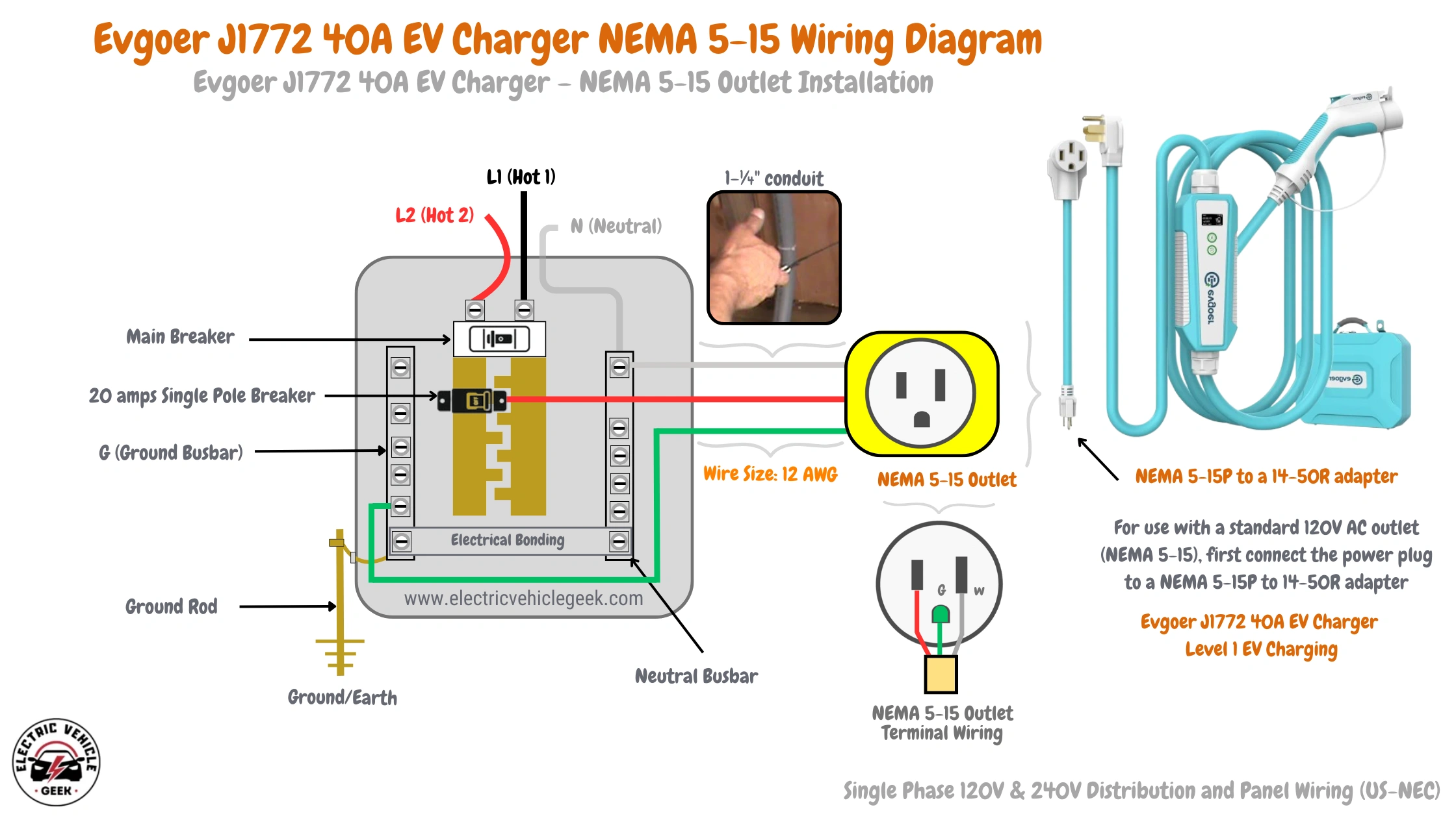
Voltage drop using EV charging adapters occurs when there is a reduction in electrical potential (voltage) along a path where current flows in a circuit, primarily due to the resistance of wires, connections, and other components. Using an EV charging adapter can increase voltage drop, especially if it is not rated for high currents. has longer cables and thinner wires, which can worsen the issue. A significant voltage drop slows charging and can overheat connections, creating safety risks.
To reduce voltage drop, use short EV charging cables for Level 1 EV charging, thick cables rated for the amperage of the EV charger, and high-quality adapters designed for EV charging. Check your adapter’s specifications to ensure it matches your charger’s power requirements.
If charging speed drops unexpectedly while using an EV charging adapter, check for heat buildup in the adapter cable and components. If charging suddenly stops, it may indicate a loose connection. We recommend ensuring that the EV charging adapter is securely plugged into both the NEMA outlet and the EV charger.
How to Check Voltage Drop in EV Charger Circuits
To check voltage drop, first measure the voltage at the service panel (breaker box).
- Level 1 EV Charger (120V): You should see a reading close to 120 volts.
- Level 2 EV Charger (240V): You should see a reading close to 240 volts.
Next, measure the voltage at the farthest point where the EV charger connects, such as the EV charger outlet for plug-n EV charger, or the Junction Box terminal for hardwired EV charger.
To find the voltage drop percentage, divide the voltage difference by the starting voltage and multiply by 100:
Voltage Drop % = [(Voltage at Panel – Voltage at Charger) / Voltage at Panel] × 100
The National Electrical Code (NEC) recommends a maximum 3% voltage drop for branch circuits supplying EV chargers, NEC 210.19(A)(1).
Example 1: Level 1 EV Charger (120V, 15A Circuit)
Scenario:
You’re installing a Level 1 EV charger (draws 12A continuously) on a 15A circuit breaker, 75 feet from the panel, using 14 AWG copper wire.
Specs:
- Voltage: 120V
- Circuit Breaker: 15A
- Charger Load: 12A (continuous)
- Wire Gauge: 14 AWG copper
- Cable Length (one-way): 75 feet
- Material: Copper
- Voltage Drop Limit: 3% of 120V = 3.6V max allowed
Voltage Drop Calculation:
Using standard voltage drop formulas or an online calculator:
14 AWG copper at 12A over 75 feet drops ≈ 3.05V
Result:
- Voltage drop % = (3.05 / 120) × 100 ≈ 2.54%
- Pass: Under 3% (acceptable for Level 1 EV charging)
Example 2: Level 2 EV Charger (240V, 40A Circuit)
Scenario:
You’re installing a Level 2 EV charger (draws 32A continuously) on a 40A breaker, 100 feet from the panel, using 8 AWG copper wire.
Specs:
- Voltage: 240V
- Circuit Breaker: 40A
- Charger Load: 32A (continuous)
- Wire Gauge: 8 AWG copper
- Cable Length (one-way): 100 feet
- Material: Copper
- Voltage Drop Limit: 3% of 240V = 7.2V max allowed
Voltage Drop Calculation:
8 AWG copper at 32A over 100 feet drops ≈ 6.17V
Result:
- Voltage drop % = (6.17 / 240) × 100 ≈ 2.57%
- Pass: Below 3% (within NEC recommendations)
Example 3: Level 2 EV Charger (Voltage Drop Too High)
Scenario:
Same setup as above, but using 10 AWG copper wire instead of 8 AWG.
Voltage Drop Calculation:
10 AWG copper at 32A over 100 feet drops ≈ 9.86V
Result:
- Voltage drop % = (9.86 / 240) × 100 ≈ 4.11%
- Fail: Exceeds the 3% limit
Fix: Upgrade to 8 AWG or reduce run length
Editor’s Tip: Use the Fluke FEV150 Analyzer for Fast, Accurate Voltage Drop Testing
If you suspect voltage drop issues in your EV charging circuit, we highly recommend the Fluke FEV150 EV Charging Station Analyzer. It provides accurate end-of-circuit voltage measurements and offers comprehensive testing to quickly identify problems.

Fluke FEV150 EV Charging Station Analyzer
We use it in our our own EV charger test bench to quickly identify issues in the branch circuit by accurately measuring power at the charging station and performing essential tests like PE pre-tests for dangerous conditions, nominal voltage and frequency checks, GFCI trip tests (basic and advanced), Control Pilot (CP) signal simulation and waveform analysis, and Proximity Pilot (PP) testing with fault simulations.
If its nominal voltage reading falls outside the acceptable range, it is a clear sign of voltage drop that can be caused by faulty wiring, improper sizing, or a poor connection. (National Electrical Code (NEC 625.41) recommends a voltage drop of less than 3%).
We recommend the Fluke FEV150 to licensed electricians and certified EV charger installers who regularly install, maintain, and troubleshoot EV charging stations.
Read our full review of the Fluke FEV150 EV Charging Station Analyzer to learn why it’s one of our top EV charging diagnostic tools, and why we recommend it to licensed electricians and certified EV charger installers
Final Thoughts
Managing voltage drop is essential for ensuring safe, efficient, and reliable EV charging. By using properly sized conductors, high-quality EV charging components, and adhering to best installation practices, you can minimize energy loss, prevent overheating, and optimize overall charging performance.
A well-designed and properly maintained EV charging setup protects your charger, accessories, vehicle, and property, while also enhancing long-term efficiency and safety.
For best results, always consult a licensed electrician or certified EV charger installer to ensure your system meets all electrical codes, safety standards, and performance requirements.

James Ndungu is a certified EV charger installer with over five years of experience in EVSE selection, permitting, and installation. He holds advanced credentials, including certification from the Electric Vehicle Infrastructure Training Program (EVITP) and specialized training in EV charging equipment and installation, as well as diplomas in EV Technology and Engineering Fundamentals of EVs. Since 2021, James has tested dozens of EV chargers and accessories, sharing expert insights into the latest EV charging technologies.