Level 3 EV Fast charging stations, unlike regular home EV chargers you might have at home, deliver electric current directly at high voltage (DC) to the battery of your electric vehicle (EV), significantly reducing charging times.
The EV Charging Station Schematics diagram below shows the key components of grid-integrated EV charging stations such as grid connection, power conversion, and multiple EV batteries connected to a DC bus with off-board chargers.
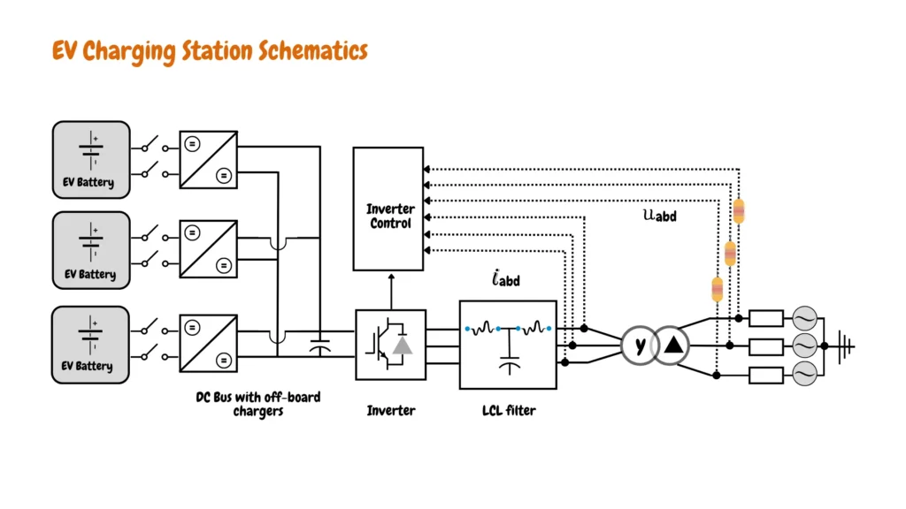
Table of Contents
How Do Fast Charging Stations Connect to the Grid?
The station connects to the electricity grid through a transformer and an LCL filter. The transformer adjusts the voltage level from the grid to a suitable level for the charging system, while the LCL filter helps to minimize electrical noise and ensure smooth power flow.
How Do Fast Charging Stations Convert AC to DC?
Fast charging stations are powered by advanced AC-DC converters tailored to the specific needs of electric vehicles (EVs). Among these, a sophisticated three-phase Voltage Source Converter (VSC) stands out, efficiently transforming AC grid power into DC for rapid battery charging.
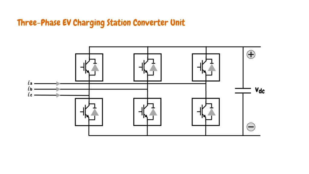
The converter’s output voltage is meticulously regulated through Pulse Width Modulation (PWM), with Insulated Gate Bipolar Transistors (IGBTs) serving as robust, high-power switches. This setup isn’t just about one-way power flow charging EV batteries, It’s designed for versatility, enabling bi-directional energy transfer that can be used for bi-directional EV charging and energy storage especially when using renewable energy for EV charging.
Fast charging stations prioritize grid harmony. A meticulously designed LCL filter acts as a silent guardian between the converter and the AC grid.
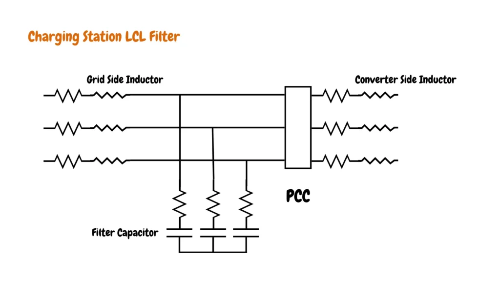
This filter specifically targets high-frequency gremlins generated by the converter’s rapid switching operation. These gremlins, known as harmonics, can disrupt sensitive grid equipment and cause power losses. As shown in the LCL filter configuration block diagram above the LCL filter consists of a converter-side inductor, a filter capacitor, and a grid-side inductor, that effectively traps these high-frequency harmonics, ensuring reliable power delivery to EVs while minimizing disruptions to the grid.
How Do Fast Charging Stations Charge EVs?
The processed DC from the converters is delivered through a central DC bus. This bus acts like a highway for electricity, allowing multiple EVs to charge simultaneously. Each EV connects to a designated slot in this DC bus using a charging cable. The integrated control system of the station monitors and manages the entire charging process, ensuring safety and optimal charging efficiency for each connected EV.
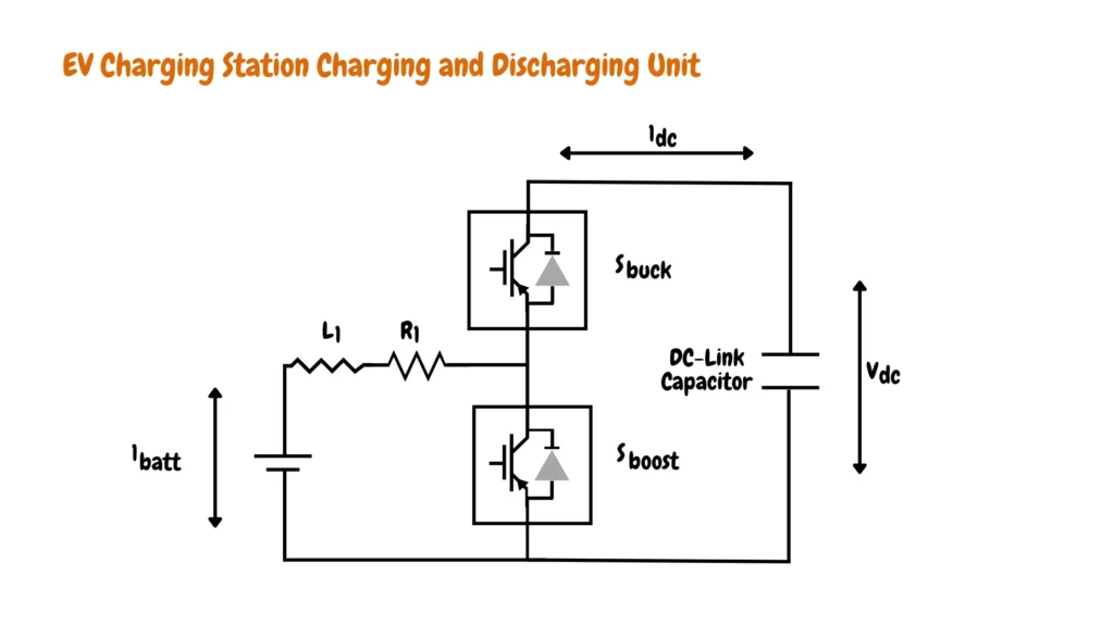
The schematic above depicts an EV charging station charging and discharging unit within a fast charging station, specifically focusing on the charging and discharging components. The incoming DC voltage from the main system (represented by “DC”) passes through an inductor (L) and resistor (R) before reaching the converter section. The converter itself consists of two switches (S1 and S2) and a DC-link capacitor. By controlling these switches, the circuit can operate in two modes:
- Boost Mode (Charging): When the battery (batt) voltage is lower than the DC-link voltage, the switches operate in a way that “boosts” the incoming DC voltage. This boosted voltage then charges the battery.
- Buck Mode (Discharging): In this mode, if the battery voltage is higher than needed (for potential future applications like vehicle-to-grid), the switches operate to “buck” or reduce the voltage. This allows the system to potentially discharge some of the stored energy from the battery back to the DC bus.
The DC-link capacitor highlighted in the fast charger charging unit block diagram above helps to smooth out any fluctuations in the DC voltage during these switching operations. This ensures a stable and efficient flow of power for charging or discharging the EV battery.

James Ndungu is a certified EV charger installer with over five years of experience in EVSE selection, permitting, and installation. He holds advanced credentials, including certification from the Electric Vehicle Infrastructure Training Program (EVITP) and specialized training in EV charging equipment and installation, as well as diplomas in EV Technology and Engineering Fundamentals of EVs. Since 2021, James has tested dozens of EV chargers and accessories, sharing expert insights into the latest EV charging technologies.