The advent of electric vehicles (EVs) has ushered in a new era of automotive technology. At the heart of this innovation is the Battery Management System (BMS), an integral component ensuring the optimal performance, longevity, and safety of EV batteries. This blog post delves into the intricacies of BMS, its functions, and its importance in the automotive industry.
Table of Contents
Understanding the Battery Management System (BMS)
The Battery Management System (BMS) is a critical electronic system in electric vehicles, responsible for monitoring and managing battery performance, safety, and longevity. Key components include hardware like the Battery Control Unit, voltage and temperature sensors, current sensors, and software algorithms that process sensor data.

Core functions of a BMS include monitoring voltage, current, and temperature, protecting the battery from operating outside safe limits, balancing cell voltages, and estimating State-of-Charge (SOC) and State-of-Health (SOH).
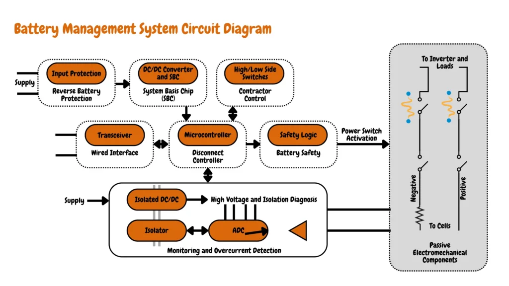
In a standard monitoring setup, a shunt resistor is connected in series with the system load to measure load current, indicated by the voltage drop across the resistor. This voltage signal is then amplified and converted to a digital format before being sent to the microcontroller (MCU). The MCU operates on the low-voltage side, while the measurement circuitry, including the amplifier and Analog-to-Digital Converter (ADC), operates on the high-voltage side. To ensure safe and reliable operation, isolation devices are employed between these circuits. The choice of isolator depends on the specific interface used for communication between the ADC and the MCU.
Key Components of a BMS
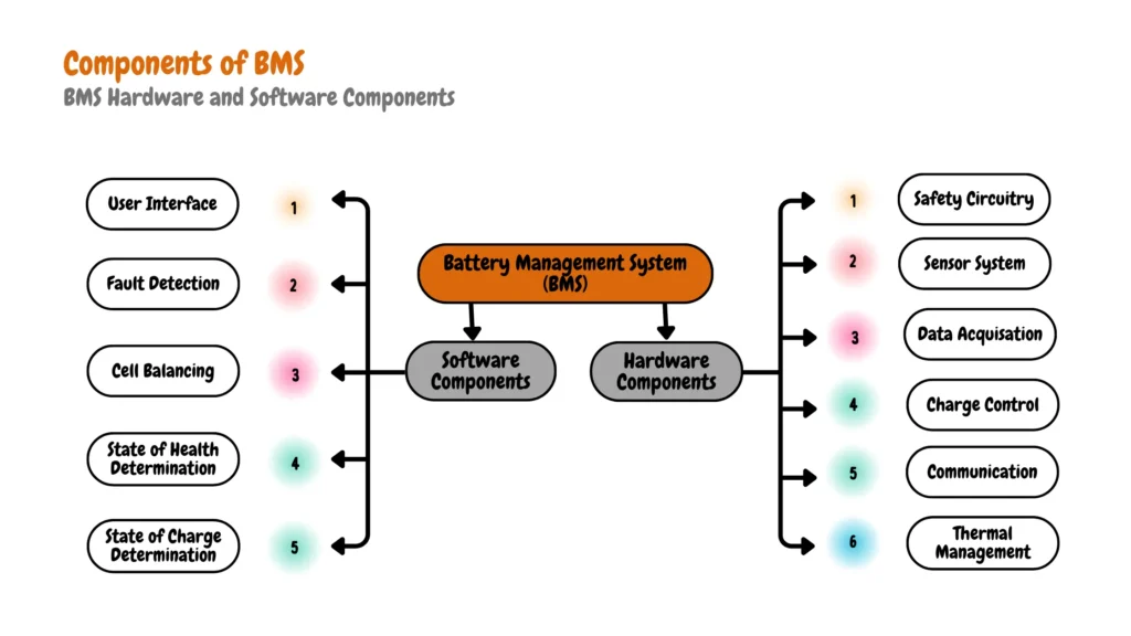
A BMS is composed of both hardware and software components, each playing a crucial role in the system’s overall function.
BMS Hardware Components
- Safety Circuitry: Improved designs include accurate alarms and controls to prevent overcharge, over-discharge, and overheating.
- Sensor System: Monitors cell voltage, battery temperature, and current. Electrochemical Impedance Spectroscopy (EIS) is proposed but limited by space and cost. Essential measurements include current, voltage, and temperature for effective state tracking.
- Data Acquisition (DAQ) and Storage: Crucial for system modeling and analysis. Charge control uses constant current/constant voltage (CC/CV) methods with a potentiostat and galvanostat.
- Cell Balancing: Variable resistors help balance cells and measure internal resistance. Communication within the BMS is typically handled by CAN Bus, allowing data transfer and interaction with users and chargers.
- Thermal Management: Critical for reducing temperature differences among cells, which impacts imbalance, reliability, and performance.
BMS Software Components
- Control and Analysis: Manages hardware operations, analyzes sensor data, and makes decisions on state estimations. Includes switch control, sample rate monitoring, and dynamic safety circuit design.
- State of Charge (SOC) and State of Health (SOH): Integrated into capability assessments using advanced algorithms like fuzzy logic and neural networks. SOC estimation is fundamental for effective cell balancing.
- Fault Detection: Intelligent data analysis identifies soft faults and out-of-tolerance conditions. Historic data aids in pre-alarm conditions.
- User Interface: Displays essential BMS information, such as remaining range based on SOC, and provides abnormal alarms and replacement suggestions based on estimations and predictions.
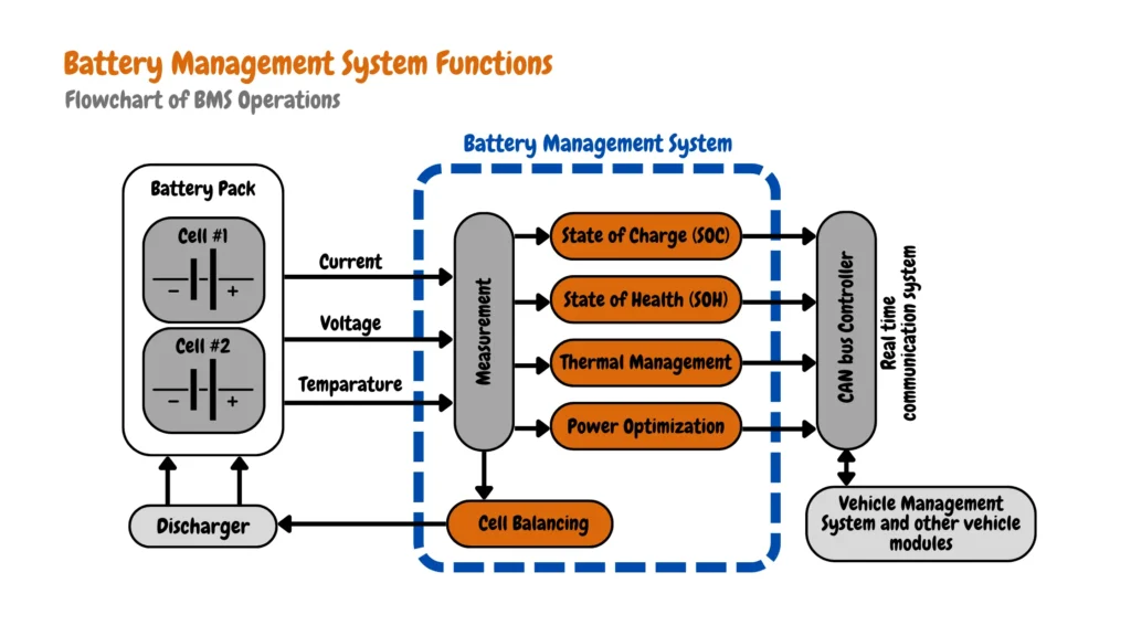
Functions of a Battery Management System
A BMS performs several critical functions to maintain battery health and efficiency.
- Monitoring: Continuously monitors voltage, current, and temperature.
- Protection: Protects the battery from operating outside its safe operating area.
- Balancing: Ensures uniform charge distribution among cells.
- State Estimation: Estimates State-of-Charge (SOC) and State-of-Health (SOH).
State-of-Charge (SOC)
State-of-Charge (SOC) is the lifeblood of electric vehicle (EV) range and performance prediction, SOC represents the remaining battery capacity as a percentage. An accurate SOC estimation hinges on a robust Battery Management System (BMS).
The BMS comprises of electronic components like the battery monitor, protector, fuel gauge, and main microcontroller (MCU) as shown in the image below, they allow the BMS to oversee battery operation. Crucially, precise SOC estimation stands as a cornerstone function of the BMS. Inaccuracies in this metric can significantly compromise battery lifespan, runtime, and even lead to critical situations like unexpected power loss.
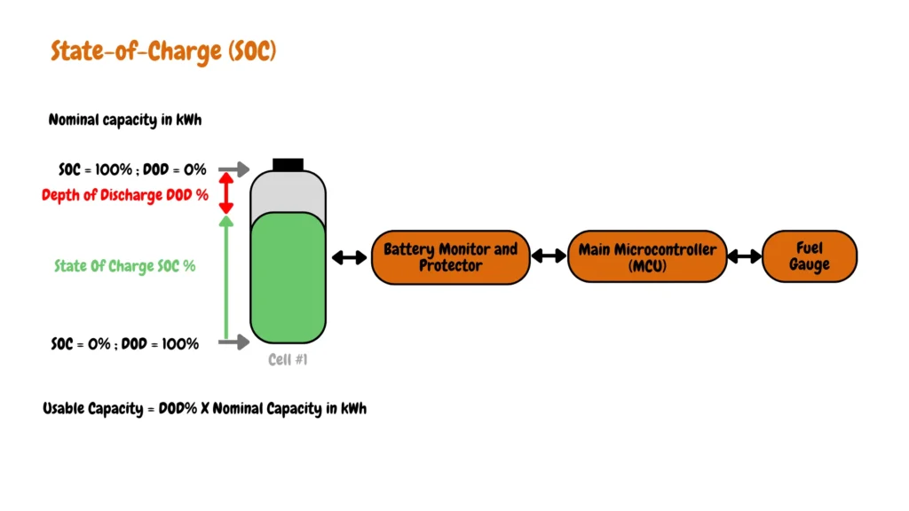
Two primary elements impact the fidelity of SOC estimation: The precision of the battery monitor’s measurements and the efficacy of the fuel gauge’s estimation algorithms.
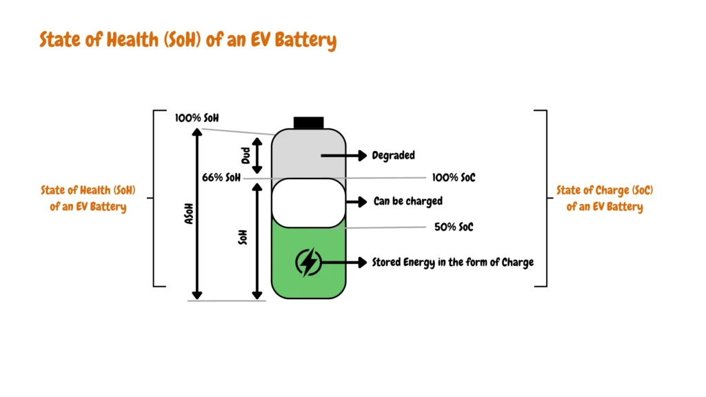
State-of-Health (SOH)
SOH reflects the current condition of an EV battery compared to its brand-new state. It encompasses factors like capacity, efficiency, and overall performance throughout the battery’s lifecycle.
Understanding Battery Health Assessment and Prediction
The state of health (SoH) of a battery is determined through a comprehensive assessment process outlined in the provided battery health assessment and prediction flowchart.
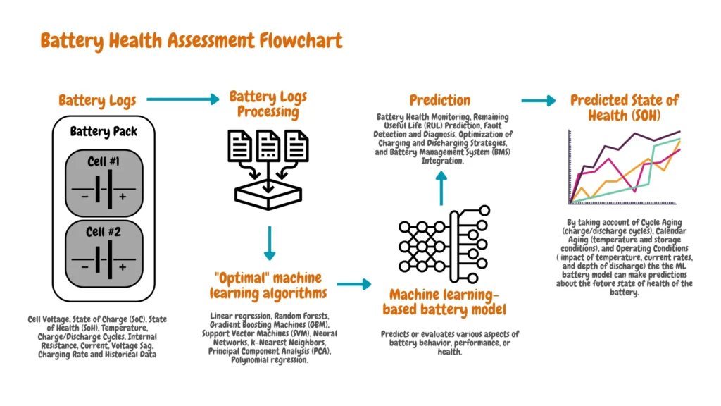
Electric vehicle battery health assessment and prediction begins with gathering battery logs, including data on cell voltage, state of charge (SoC), temperature, charge/discharge cycles, and more. These logs are then processed to extract relevant information for analysis.
Machine learning algorithms, such as linear regression, random forests, and neural networks, are employed to predict the SoH based on various factors like cycle aging, calendar aging, and operating conditions. The predicted SoH is derived by considering the impact of factors such as temperature, current rates, and depth of discharge on battery degradation over time.
This holistic approach enables proactive maintenance, accurate prediction of remaining useful life, fault detection, optimization of charging/discharging strategies, and seamless integration with battery management systems (BMS), ensuring optimal performance and longevity of the battery in diverse applications such as electric vehicles and renewable energy storage.
Monitoring SOH is essential as it directly impacts the range, performance, and safety of electric vehicles.
Factors that contribute to the gradual decline in State-of-Health (SOH)
- Cycle Life: Every charge-discharge cycle takes a toll on the battery. Lithium-ion batteries have a finite number of cycles before capacity loss begins.
- Temperature Extremes: Extreme hot or cold temperatures accelerate battery degradation. High temperatures can lead to electrolyte breakdown and thermal runaway, while low temperatures increase internal resistance.
- Depth of Discharge (DoD): Regularly draining the battery to very low levels can expedite its decline. Batteries last longer when operated within a specific state of charge window.
- Charging Rate: Fast charging generates heat, impacting lifespan. Managing charging rates and implementing cooling mechanisms are crucial for preserving battery health.
- Chemical Degradation: Chemical reactions during charge and discharge cycles can form unwanted byproducts, reducing capacity and efficiency.
- Calendar Aging: Even unused batteries degrade over time due to internal chemical processes.
Methods of monitoring State-of-Health (SOH)
- Capacity Measurement: Regularly measuring the battery’s capacity reveals its declining ability to hold a charge.
- Impedance Spectroscopy: By measuring a battery’s impedance at various frequencies, researchers can assess its internal health and electrochemical properties.
- Voltage and Current Analysis: Monitoring voltage and current during charging and discharging cycles can reveal changes in battery behavior, indicating potential health issues.
- Thermal Monitoring: Tracking battery temperature helps identify potential thermal issues impacting SOH.
Benefits of State-of-Health (SOH) Monitoring
- Enhanced Range Estimation: Battery degradation directly impacts driving range. SOH monitoring helps owners estimate the remaining range more precisely.
- Maximized Efficiency: Degraded batteries lose efficiency, wasting energy as heat. Maintaining good SOH improves overall efficiency.
- Prioritized Safety: Batteries nearing the end of their lifespan can become unstable, posing safety risks. Monitoring SOH helps detect potential safety concerns.
- Cost-Effective Management: Replacing an EV battery is expensive. SOH monitoring allows owners to plan for battery replacement strategically.
Cell Balancing
Cell balancing is a vital function of the BMS, ensuring that all cells in the battery pack maintain the same voltage. This process maximizes the battery pack’s capacity and extends its lifespan.
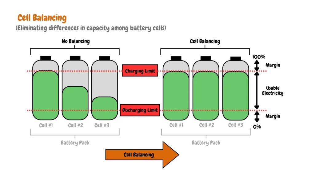
Achieving balanced charge and discharge across individual cells remains a critical, yet often inadequately addressed, challenge in Battery Management Systems (BMS). It’s paramount to extend battery lifespan, as cell imbalance leads to premature degradation and reduced overall capacity.
Manufacturing tolerances ensure no two cells are identical. Slight variations in capacity exist. Cells with lower capacities discharge faster, becoming stressed and susceptible to damage. Conversely, cells with higher capacities remain partially unused, hindering overall pack performance. During charging, weaker cells reach full capacity first, limiting the charge received by stronger cells.
Cell balancing actively addresses these imbalances, significantly enhancing overall battery capacity. By ensuring all cells contribute equally, the pack’s usable capacity transcends the limitations of the weakest cell. Furthermore, cell balancing safeguards these weaker cells from over-discharge and over-charge, preventing damage that could lead to short circuits, leaks, and ultimately, catastrophic battery pack failure.
One could define cell balancing as the optimization of usable battery capacity by mitigating cell-to-cell capacity variations. When voltage discrepancies exist between cells in a series-connected pack, their ability to reach full charge or discharge depth is compromised. This effectively reduces their practical capacity. Cell balancing safeguards against this phenomenon, ensuring all cells contribute maximally to the pack’s performance. In series-connected cell configurations within a BMS, cell balancing becomes an indispensable function for maximizing overall battery performance and lifespan.
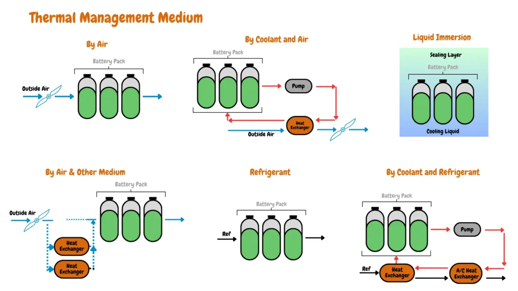
Thermal Management
Managing the temperature of the battery pack is crucial for safety and performance. A BMS employs various thermal management strategies, including air cooling, liquid cooling, phase change materials, and more.
Conclusion
A well-designed Battery Management System is essential for the efficient and safe operation of electric vehicles. By continuously monitoring and managing various parameters, a BMS ensures that the battery performs optimally and remains within safe operational limits.