At Electric Vehicle Geek, we geek out over more than just the specs of an EV charger; we actually open them up to see what’s inside. By examining the internal components and judging their features and quality, we bring a deeper level of insight to our EV charger reviews. This hands-on, geeky process makes our ratings and reviews more detailed and accurate, ensuring our readers get the best EV chargers possible.
Table of Contents
What Is Inside an EV Charger?
The electrical schematic below illustrates the internal components of a typical 240V home EV charger, from the power input to the output connector.
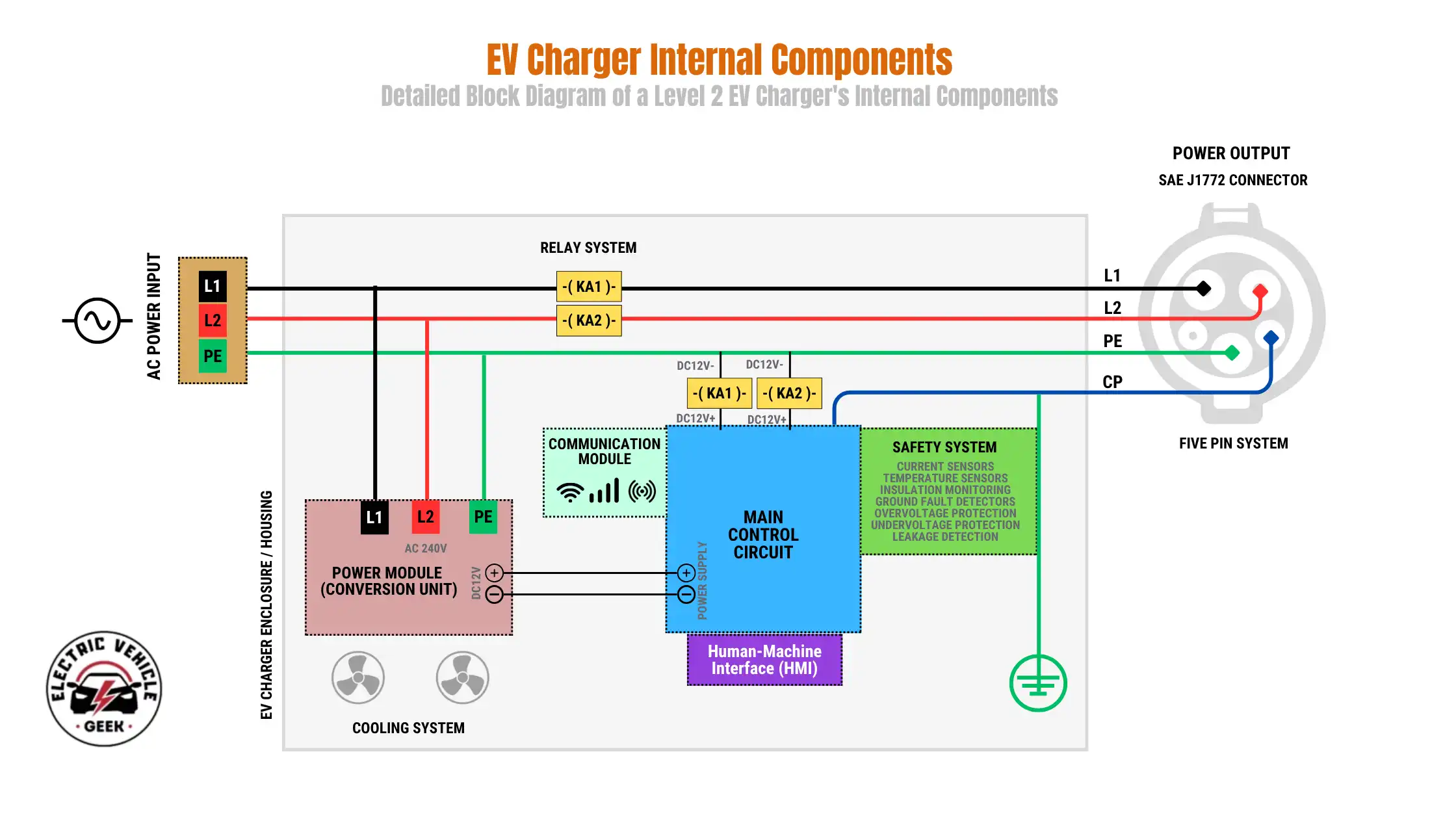
The diagram illustrates how the key internal components of an EV charger, including the power module, main control circuit, communication module, safety system, cooling elements, relay system, and user interface, are interconnected and function together.
WARNING: EV Charger Contains High Voltage Components!
Do not attempt to open, disassemble, modify, or transform an electric vehicle charger. The internal components carry lethal, high-voltage electricity, even when the unit is not actively charging, posing a severe risk of electric shock, fire, and death. Servicing or opening the enclosure must only be performed by a qualified, licensed professional.
Main Components Inside an EV Charger
Now that you have an overview of the key internal parts of an EV charger, let’s take a closer look at each component to understand its role and how it contributes to safe and efficient charging.
Power Input Stage
This is where the charger connects to your home’s electrical grid (AC mains). It’s the first line of defense, typically including essential components like fuses, circuit breakers, surge protectors, and EMI filters. These elements work together to shield the charger and your vehicle from electrical surges, noise, and short circuits, ensuring a clean and protected power supply.
Printed Circuit Board (PCB)
At the heart of every EV charger is the printed circuit board (PCB), which serves as the central platform where the internal parts of an EV charger are mounted and interconnected. The PCB provides the physical structure and the circuit pathways that allow signals and power to flow between the charger’s different systems, including the power electronics, control circuits, safety mechanisms, and communication modules, as shown in the Emporia home EV charger PCB below.
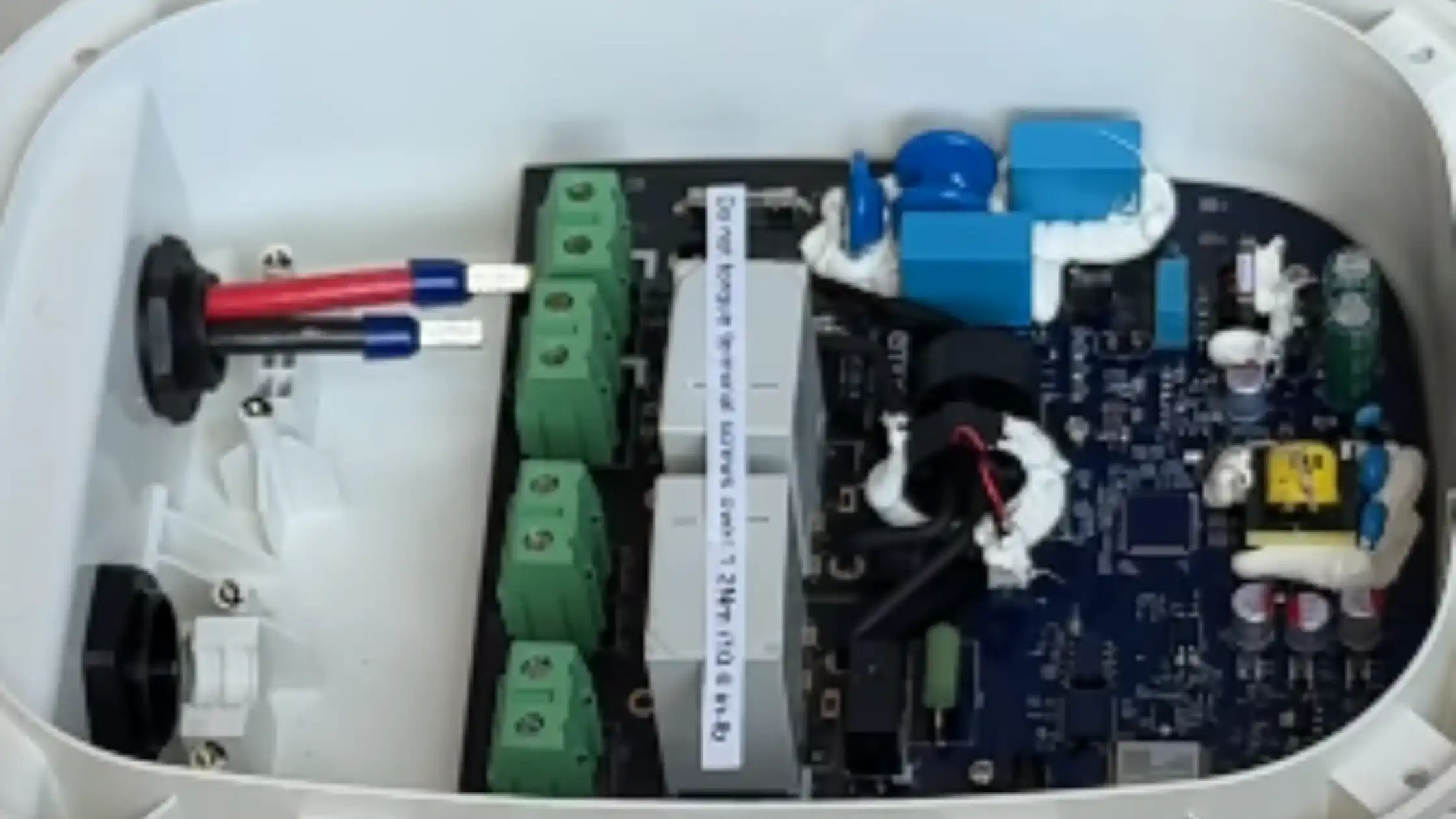
In EV chargers, the PCB is designed to handle high current loads while maintaining safety, efficiency, and thermal stability. Its layered design incorporates copper traces, insulation, and protective coatings to ensure reliable performance under varying environmental and electrical conditions. While reviewing EV chargers, we check on the quality of the PCB and its design, which directly affects the durability and efficiency of the charger, as poor design or materials can lead to overheating, signal interference, or premature failure.
Modern smart chargers often include multiple PCBs to separate different EV charging functions. For example, one board may handle power conversion, while another manages communication and control. This modular approach improves reliability, simplifies manufacturing, and makes maintenance easier. In premium chargers, PCBs are reinforced with conformal coatings or epoxy potting for additional protection against moisture, dust, and vibration, especially in outdoor-rated units.
Power Module (Power Conversion Unit)
The heart of electricity conversion and conditioning.
- AC chargers’ power modules act as a sophisticated safety switch and communication bridge. They relay AC power safely from your home’s electrical panel directly to your car. The actual conversion of AC to DC power happens within the vehicle’s onboard charger.
- DC fast chargers’ power modules are much more complex, performing the heavy lifting of converting AC grid power into high-voltage DC power that the EV can accept directly. This involves rectifiers to change AC to DC and powerful DC/DC converters to step down the voltage to the car’s battery requirements.
Main Control Circuit (Controller/Logic Board)
This is the “brain” of the EV charger. It handles crucial communication with the electric vehicle using standardized charging protocols (like J1772 for North America). It precisely controls the relays/contactors, manages the charging speed based on vehicle requests and grid availability, and continuously monitors safety parameters.
Contactor / Relay System
These are robust electrical switches designed to connect and disconnect the high-power lines between your home and the EV safely. They are entirely controlled by the main circuit, ensuring that power only flows when all safety checks are cleared and communication with the vehicle is established.
Cooling System
While less critical for lower-power home chargers, cooling becomes essential for higher-power units (especially 50 kW and above). This system, often comprised of fans or even liquid cooling, prevents the power electronics from overheating during prolonged charging sessions, which can generate significant heat.
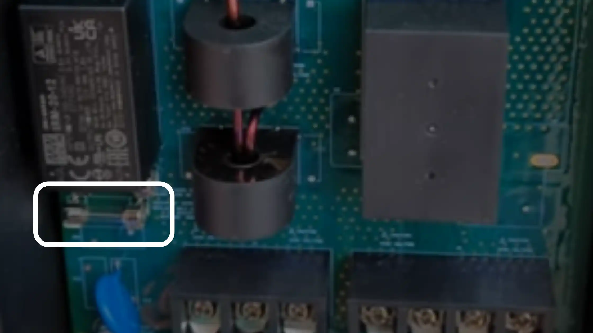
Sensors & Protection Circuits
Safety is paramount in EV charging, which is why modern chargers are designed with multiple built-in safety features. These include fuses and current sensors that detect overcurrents, insulation monitoring systems that check for electrical leaks, and ground fault detectors that protect against shocks.
High-amperage EV chargers, such as the Autel MaxiCharger 80A EV charger, are engineered to operate safely while delivering up to 80 amps of continuous load for extended periods. They are built to handle demanding charging sessions even in high ambient temperatures up to 113℉. To ensure reliability, these chargers also feature internal temperature monitoring systems that track heat levels in real time. If overheating or any abnormal condition is detected, the safety circuits automatically shut down charging to protect both the equipment and the user.
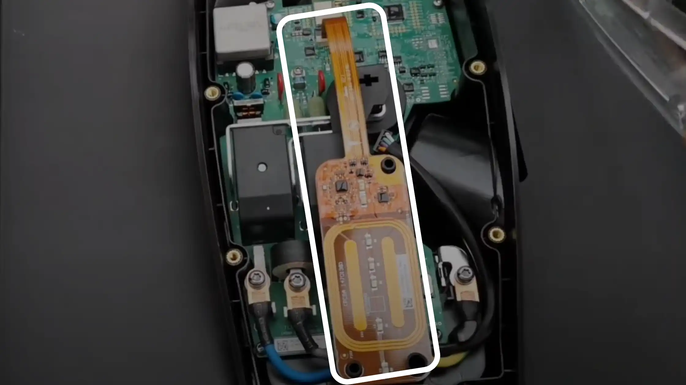
Human-Machine Interface (HMI)
The user interface is how you interact with your EV charger, and it varies widely by model. Some home EV chargers, such as the Tesla Wall Connector, use an integrated Human-Machine Interface (HMI) instead of an LED display. This HMI features capacitive touch sensors and multi-color LED indicators embedded within the front enclosure. The LEDs provide clear charging status feedback, including standby, charging in progress, and fault detection, while the touch-sensitive surface enables user interaction without mechanical buttons.
Others, like the ApexCharger MACH 2 EV charger, include a larger 4 ¾-inch LED display panel that provides detailed charging statistics, error notifications, and energy usage data. High-end chargers may even feature full-color touchscreens, offering advanced settings, smart controls, and real-time monitoring directly from the unit.
Communication Module
The communication module is what makes an EV charger truly “smart.” It provides connectivity features such as Bluetooth, Wi-Fi, Ethernet, or even 4G/5G, which allow the charger to link with smartphone apps, charging networks, and utility systems for smart grid integration.
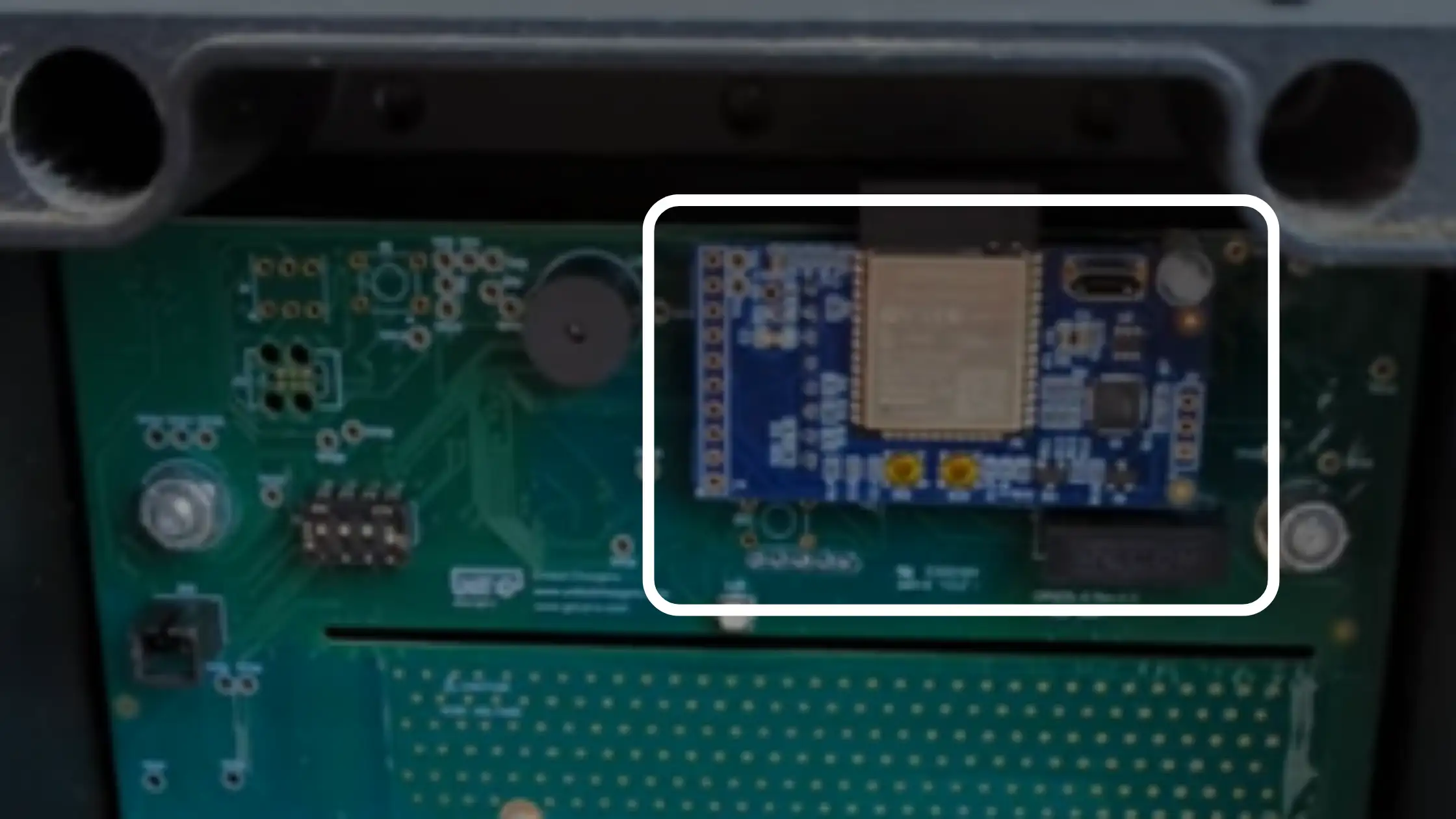
The Wi-Fi module is strategically placed at the top of the unit to optimize wireless signal strength and minimize interference from other components. This placement ensures reliable data transmission and reception, allowing the charger to perform critical smart functions such as remote monitoring, charging schedules, and over-the-air updates with greater consistency.
The design and integration of communication modules can vary across smart EV chargers. In the case of the Grizzl-E Smart EV Charger, the module is implemented as a compact PCB strategically positioned within the unit, as shown below.
Some home chargers designed for multiple users also include RFID readers for secure access and user tracking. The Autel MaxiCharger Home Smart AI is a good example, as it combines wireless connectivity with RFID authentication, making it practical for shared residential or commercial use.
Advanced and latest smart EV chargers like the Autel MaxiCharger 80A EV charger take communication even further with support for Wi-SUN dual networks. Wi-SUN, short for Wireless Smart Utility Network, is a standard based on IEEE 802.15.4g that was developed for modern smart grids, smart meters, EV chargers, and other utility systems. It is optimized for long-range, secure, and low-power mesh networking, making it ideal for heavy-duty charging environments.
Dual-network capability means the charger can connect to two Wi-SUN networks simultaneously. One network typically links to the utility or smart grid for functions such as demand response, load balancing, and real-time energy pricing. The other connects to a local controller or nearby chargers to coordinate site-level energy use, such as balancing loads when several chargers share one electrical panel. This setup provides redundancy and reliability; if one network fails or becomes overloaded, the charger can continue operating through the second.
Enclosure / Housing
Although not an internal component, we felt it was important to discuss the EV charger enclosure and its role in protecting the internal components as well as ensuring overall safety and durability.
The enclosure, or housing, is the protective shell that surrounds every EV charger. Its role goes far beyond aesthetics; it provides electrical insulation, prevents accidental contact with live parts, and creates a controlled pathway for cable entry and exit. By sealing off and shielding sensitive electronics, the enclosure ensures the internal components remain protected from dust, moisture, impact, and other environmental stresses.
The design and rating of the housing determine whether a charger is suited for indoor-only installations or capable of withstanding the rigors of outdoor environments. For example, outdoor-rated chargers, such as the Autel MaxiCharger, utilize a NEMA 4 certified enclosure with CSA approval, providing reliable protection against rain, snow, and dust while ensuring safe operation across a wide range of climates.
In addition to its protective role, the enclosure carries essential external labeling, safety warnings, and certification markings. These identifiers communicate voltage, amperage, and wiring requirements, while third-party approvals such as UL, CSA, or ETL confirm that the unit complies with rigorous electrical and safety standards. The housing also influences installation and mounting, as reinforced brackets, watertight seals, and accessible wiring compartments are necessary to allow secure wall or pedestal placement without compromising the charger’s weatherproof integrity.
Charging Cable & Connector
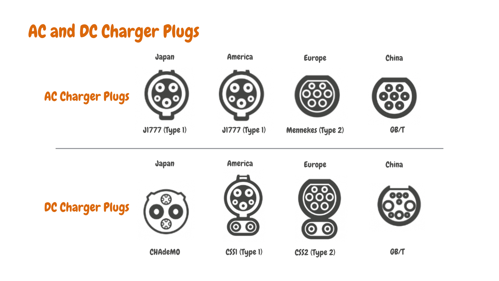
The charging cable and connector are the physical interface between your EV and the charger, governed by electric car charging standards that ensure interoperability between supply equipment and vehicles. Common EV charger connectors include J1772, CCS, CHAdeMO, and Tesla’s NACS.
These connectors do more than deliver power; they also carry critical safety signals. Built-in “pilot signal” and “proximity” pins enable communication between the vehicle and the charger, allowing them to perform a secure handshake, verify compatibility, and negotiate charging parameters before current begins to flow.

James Ndungu is a certified EV charger installer with over five years of experience in EVSE selection, permitting, and installation. He holds advanced credentials, including certification from the Electric Vehicle Infrastructure Training Program (EVITP) and specialized training in EV charging equipment and installation, as well as diplomas in EV Technology and Engineering Fundamentals of EVs. Since 2021, James has tested dozens of EV chargers and accessories, sharing expert insights into the latest EV charging technologies.