This guide comprehensively covers split-phase EV charger installation. In residential settings in the United States, electrical systems commonly use split-phase distribution.
This setup involves two hot wires (typically black and red), one neutral wire (usually white), and one ground wire (typically green or bare copper). Each hot wire carries 120 volts relative to the neutral wire, making it effectively a 240-volt split-phase system.
The split-phase system configuration system is a common residential electrical system configuration that supports standard 120V single-phase EV charger installation as well as 240V Split-Phase EV Charger Installation. It’s well-suited for installing Level 1 EV chargers operating at 120V, as well as Level 2 EV chargers operating at 240V.
Table of Contents
Split-Phase Electrical Panel Wiring Diagram
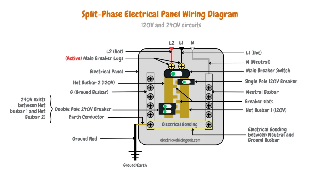
The illustrative image above shows a split-phase electrical panel wiring diagram for 120V and 240V circuits, three wires are entering the main panel from the energy meter.
- 120V L1 (Hot) = Black color
- 120V L2 (Hot 2) = Red color (for illustration purposes only)
- N (Neutral) = White color
The two hot wires are connected to the main electrical panel circuit breaker with active main breaker lugs, from the main electrical panel circuit breaker the hot current is transferred to hot busbars labeled hot busbars 1 and 2, each busbar carries 120V and 240V between the two busbars.
As shown in the split-phase electrical panel wiring diagram above the neutral wire is connected to the neutral busbar which bonds (electrical bonding) with the ground busbar, the neutral wire and neutral busbar both carry 0V.
To ensure proper grounding for the EV charger, both the neutral busbar and the ground busbar in the electrical panel are bonded together. Additionally, an earth connector runs from the ground busbar to a ground rod specifically for grounding the EV charger.
120V Single-Phase EV Charger Installation
Below we have outlined the steps for 120V single-phase EV charger installation in single-home EV charger installations.
120V single-phase EV charger installations are commonly used in Level 1 EV charging which require plugging in a 120V Level 1 EV charger such as the Lectron Level 1 EV charger to a 120V electric vehicle branch circuit.
How to Wire a 120V Single-Phase EV Charger Installation
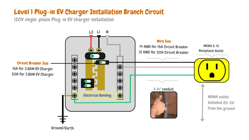
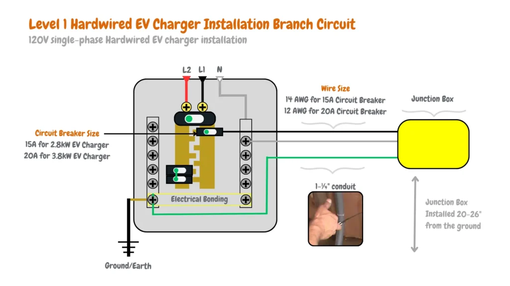
To install a Level 1 EV charger you will need to mount a single pole EV charger circuit breaker to any of the hot busbars breaker slots depending on the power rating of the EV charger (kW). A 2.8 kW Level 1 EV charger will require a 15A dedicated EV charger circuit breaker, and a 3.8 kW Level 1 EV charger will require a dedicated 20A EV charger circuit breaker.
To install a 2.8 kW Level 1 EV charger in a 120V single-phase EV charger installation, we prefer to use the Siemens Q115 15-Amp single pole type QP circuit breaker.

For a 3.8 kW Level 1 EV charger single-phase EV charger installation, we prefer to use the Siemens Q120 20-Amp single pole type QP circuit breaker.

To learn more about Siemens circuit breakers, and their application in EV charging, please read our guide on Siemens EV Charger Circuit Breakers or if you would like to understand all about EV charging circuit breakers check out our guide on Electric Vehicle Charger Circuit Breaker Selection Guide
You will then be required to wire the single-pole EV charger circuit breaker to the NEMA 5-15R for plug-in 120V level 1 EV charger installations as shown in the NEMA 5-15R wiring diagram below:
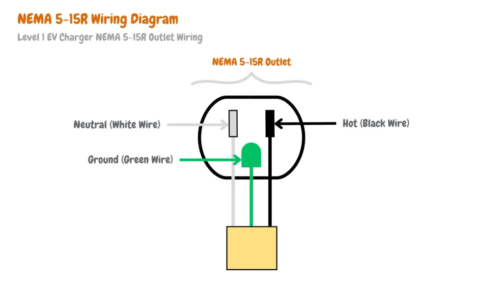
A NEMA 5-15R is a standard 120V electrical outlet in the United States that operates on a single-phase electrical system, providing 120 volts of alternating current (VAC) to plug-in EV charger installations.
To connect the NEMA 5-15R with its circuit breaker, you will need the correct electric vehicle branch circuit wire size depending on the power rating of the EV charger and the dedicated circuit breaker used, for A 2.8 kW Level 1 EV charger using a 15A dedicated EV charger circuit breaker you will need 14 AWG (2.08 mm²) wires, and 12 AWG (3.31 mm²) wire size for a 3.8 kW Level 1 EV charger secured by a dedicated 20A EV charger circuit breaker.
The wire should have a green ground wire that should be connected to the ground terminal of the NEMA 5-15R and the ground bus of the electrical panel for proper Level 1 EV charger grounding.
At the end of the installation, your 120V single-phase Plug-in EV charger installation will look similar to the Level 1 Plug-in EV charger installation branch circuit below:
For Level 1 hardwired EV charger installations (not common), your 120V single-phase electric vehicle branch circuit will connect with the EV charger terminals at a junction box as shown in the Level 1 hardwired EV charger installation branch circuit below:
240V Split-Phase EV Charger Installation
Our 240V split-phase EV charger installation will show you how to install a Level 2 Fast EV charger that requires 240V of current, 240V split current EV charger installation is also referred to as 240V single-phase EV charger installation and should be used to connect to a single load point such as an EV charger.
How To Wire a 240V Split-Phase EV Charger Installation
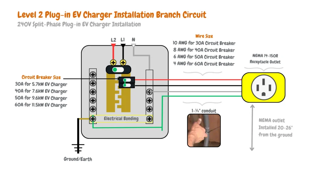
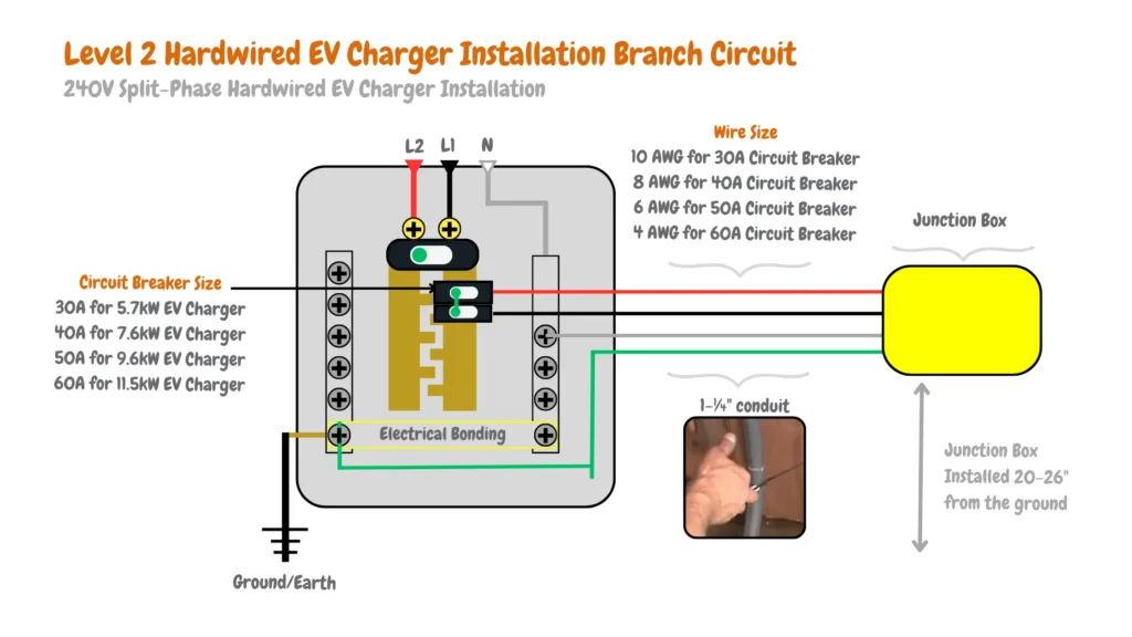
To install a level 2 EV charger to a 240V split current you will need a dedicated two-pole EV charger circuit breaker that mounts between the two hot busbars 1 and 2 in a split phase electrical panel since each hot busbar has 120V, combined they make up 240V required to power a Level 2 EV charger such as the Enphase IQ 50 EV Charger, depending on the power rating of the EV charger you will need anywhere between 30A to 100 A double pole circuit breakers.
Below we have created a table for you to make it easy to purchase the right two-pole EV charger circuit breaker depending on the power rating of your Level 2 EV charger.
| Two-Pole EV Charger Circuit Breaker | Recommended EV Charger Circuit Breaker | Power Rating of Level 2 EV Charger (kW) |
|---|---|---|
| 30 | SIEMENS Q230 30-Amp Double Pole Type QP Circuit Breaker | 5.7 |
| 40 | Siemens Q240 40-Amp Double Pole Type QP Circuit Breaker, Black | 7.6 |
| 50 | Siemens Q250 50 Amp Double Pole Type QP Circuit Breaker | 9.6 |
| 60 | Siemens Q260 60 Amp Double Pole Type QP Circuit Breaker | 11.5 |
| 100 | Siemens Q2100 100 Amp Double Pole Type QP Circuit Breaker | 19.2 |
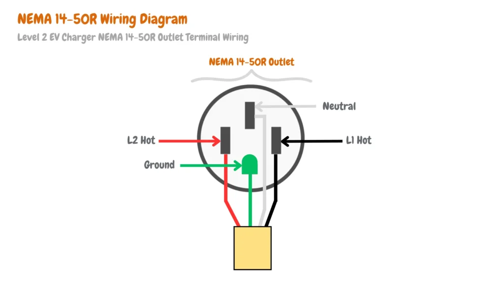
You will also need two output wires from the double pole circuit breaker and connect them EV charger to the NEMA 14-50R receptacle outlet or a hardwired EV charger junction box depending on whether you have a Plug-in Level 2 EV charger or a hardwired Level 2 EV charger, the wire should include a ground wire that should connect from the NEMA 14-50R ground terminal to the electrical panel ground bus.
The illustrative image below shows how to wire the NEMA 14-50R receptacle outlet two hot wired and the ground wire.
To connect the dedicated two-pole EV charger circuit breaker to the NEMA 14-50R receptacle outlet or the level 2 EV charger branch circuit junction box, you will require the right wire size depending on the power rating of your Level 2 EV charger and the dedicated dual pole circuit breaker used, The table below will guide you on the correct wire size of your 240V split-phase EV branch circuit:
| EV Charger Wire Gauge | EV Charger Wire Size (mm²) | Electric Vehicle Branch Circuit Breaker | Power Rating of EV Charger (kW) |
|---|---|---|---|
| 10 AWG | 5.26 mm² | 30 Amp Circuit | 5.7 kW |
| 8 AWG | 8.36 mm² | 40 Amp Circuit | 7.6 kW |
| 6 AWG | 13.30 mm² | 50 Amp Circuit | 9.6 kW |
| 4 AWG | 21.15 mm² | 60 Amp Circuit | 11.5 kW |
At the end of your 240V split-phase plug-in EV charger installation, your electric vehicle branch circuit should look similar to the 240V split-phase Plug-in EV branch circuit diagram below:
For the hardwired Level 2 EV charger, your 240V split-phase EV charger installation will connect to the Level 2 EV charger at the junction box as shown in the hardwired Level 2 EV charger 240V split-phase EV branch circuit diagram below:
Conclusion
Installing a split-phase EV charger involves careful consideration of electrical panel configurations and wiring specifications. Whether opting for a 120V single-phase setup or a 240V split-phase system, adherence to local electrical codes and manufacturer guidelines is crucial to ensure safety and optimal performance.
The provided wiring diagrams and installation steps serve as foundational guides, emphasizing the importance of proper grounding, breaker sizing, and voltage compatibility. By following these procedures diligently, electric vehicle owners can effectively and safely integrate charging solutions into their residential electrical systems, contributing to both convenience and sustainability in transportation.

James Ndungu is a certified EV charger installer with over five years of experience in EVSE selection, permitting, and installation. He holds advanced credentials, including certification from the Electric Vehicle Infrastructure Training Program (EVITP) and specialized training in EV charging equipment and installation, as well as diplomas in EV Technology and Engineering Fundamentals of EVs. Since 2021, James has tested dozens of EV chargers and accessories, sharing expert insights into the latest EV charging technologies.
Last update on 2026-06-11 / Affiliate links / Images from Amazon Product Advertising API