Since 2021, we’ve been building a dedicated EV charger test bench in our small workshop. Now we’re ready to show you how we built it, what EV chargers and EV charging accessories we test, the test equipment we use, how everything works, and the upgrades we’re planning as we move toward a professional-grade testing environment.
We set out to build a single-phase (120V/240V) versatile test platform that supports both 120V Level 1 and 240V Level 2 EV chargers, along with a wide range of EV charging accessories we review here at Electric Vehicle Geek.
Our setup simulates real-world residential EV charger (AC) installations and is designed to be as flexible as possible. We can swap key electric vehicle charger branch circuit components, including dedicated circuit breakers, conductors, NEMA outlets, and other related hardware as needed, to test a wide variety of installation scenarios.
These range from standard Level 1 home charging and Level 2 home charging equipment to more advanced configurations, including solar EV chargers for solar-integrated EV charging and bi-directional EV charging systems such as vehicle-to-home (V2H) and vehicle-to-grid (V2G).
Beyond flexibility, this test bench was meticulously engineered to comply with strict electrical safety standards and key provisions of the National Electrical Code (NEC).
Table of Contents
Main Panel and Feed
The system begins with a single service drop or lateral originating from the utility transformer. This transformer is typically supplied by a high-voltage primary conductor and a neutral from the utility line. On the secondary side, it delivers two 120V hot conductors and a neutral, providing 240V split-phase power to the service drop. This feeds a dedicated 200-amp main breaker panel, purpose-built for EV charger branch circuit testing.
A 200-amp panel gave us sufficient capacity to power not only the dedicated Electric Vehicle Supply Equipment (EVSE) branch circuit, but also several high-current circuits for EV charging accessories and specialized charger stress-testing equipment. These test components include an EV load emulator (a simulated EV), environmental chambers for temperature and humidity control, safety testing equipment, communication protocol emulators, instrumentation and measurement systems, and control and automation hardware, which we will highlight in the section below.
Some of these EV charging test systems have already been integrated into our setup, while others are in the process of being added. As we expand our testing capabilities, we’ll be able to conduct more advanced EV charging performance evaluations, simulate a wider range of real-world charging scenarios, and generate deeper technical insights.
Be sure to check back regularly for updates to our existing EV charger reviews and EV charging accessories reviews, and new reviews featuring expanded test data and analysis.
Our 200-amp panel is configured for a split-phase distribution system, the standard for residential and light commercial service in North America. This setup conveniently provides both 120V and 240V circuits, enabling us to test Level 1 (120V) and Level 2 (240V) EV chargers commonly used in residential installations. The main breaker serves as the primary overcurrent protection device for the entire test bench, safeguarding the system against electrical faults and overload conditions.
Looking ahead, we plan to incorporate a programmable AC power supply into our setup. This would allow us to simulate grid fluctuations, voltage drops, and frequency shifts, ideal for testing how EV chargers and utilities respond to imperfect utility power. It’s an essential upgrade for evaluating how well EVSEs maintain performance and safety in less-than-ideal conditions.
EV Charger Branch Circuits
To create a versatile test bench capable of evaluating a wide range of EV chargers that we review, with varying amperage, power requirements, and connection types, we implemented three modular EVSE branch circuits, as shown in our EV charger test bench circuit wiring diagram below:
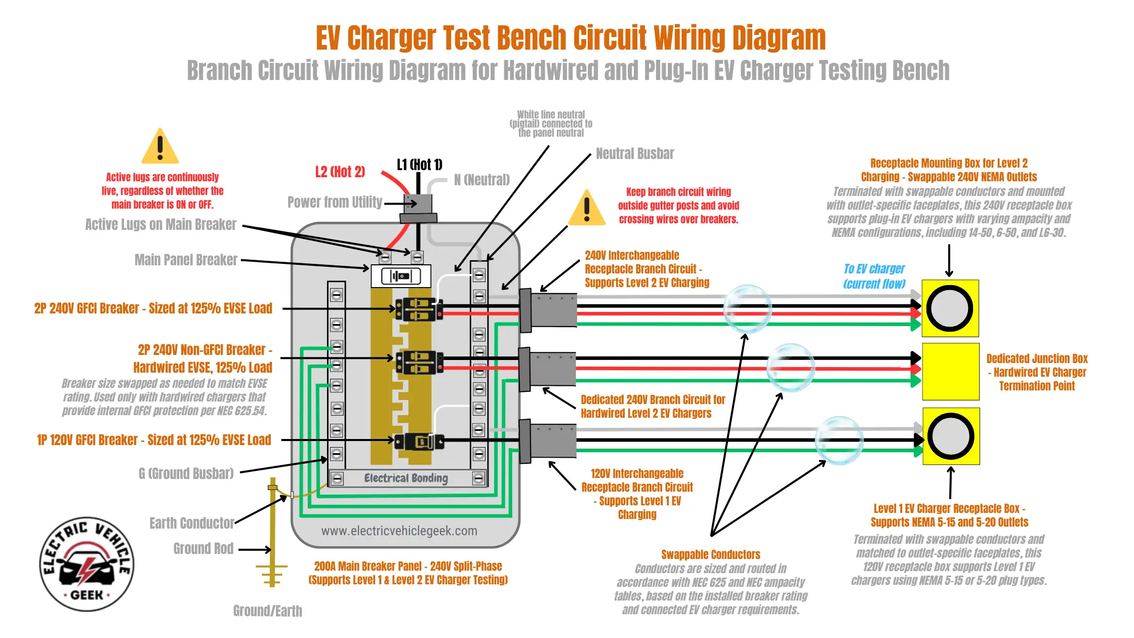
Each EV charger branch circuit in our test bench was designed with a modular architecture to accommodate the wide range of EVSE available on the market. This modularity allows for quick swapping of key branch circuit components, including dedicated EV charger breakers, varying wire gauges, NEMA outlets, and junction boxes, to support a broad spectrum of amperage requirements. This is especially valuable for testing EV chargers with adjustable current settings, enabling the charger’s output to be fine-tuned for different installation scenarios.
By supporting component interchangeability, this setup enhances compatibility with various EV charging loads and future-proofs the system without necessitating costly panel upgrades. It also ensures safe operation by preventing circuit overloading, thereby reducing the risk of overheating or fire. Ultimately, this modular approach enables the test bench to be easily reconfigured for evolving EVSE standards and installation practices, making it highly adaptable for both current and future testing requirements.
Our modular EV charger branch circuits, built with interchangeable electrical components, also enable us to test a broad range of EV charging accessories reviewed here at Electric Vehicle Geek. These include dedicated circuit breakers for EVSE, surge protection devices, conductors for EV charger installations, NEMA plug-in outlets, outlet splitters, weatherproof outlet covers, and EV charger extension cords.
This flexibility ensures our testing reflects real-world installation scenarios and product performance under varying electrical conditions.
Level 1 Plug-in Charger Circuit
Testing Level 1 EV chargers requires a dedicated 120V branch circuit, configured to support both NEMA 5-15 and NEMA 5-20 receptacles used in Level 1 EV charging. The circuit is protected by a single-pole GFCI breaker, rated at either 15 amps or 20 amps, depending on the receptacle and charger under evaluation.
Level 1 EV charger wire sizes are selected based on NEC Table 310.16 and breaker ratings: we use swappable solid copper conductors, 14 AWG (≈ 2.08 mm²) for 15A circuits and 12 AWG (≈ 3.31 mm²) for 20A circuits. These are routed from the GFCI breaker to the 125V receptacle box, ensuring correct ampacity and minimal voltage drop under load.
This configuration provides a safe, code-compliant platform for evaluating Level 1 EVSEs while meeting the GFCI protection requirements of NEC 210.8(A) for 125V residential receptacles.
Level 2 Plug-in Charger Circuit
For testing plug-in Level 2 EV chargers, we implemented a dedicated 240V branch circuit protected by a two-pole GFCI breaker. The breaker’s ampacity is carefully selected to match the rated output of the EVSE under test, typically 15, 20, 30, 40, or 50 amps, per NEC 210.20(A) for overcurrent protection and NEC 625.41, which mandates GFCI protection for all EVSE-connected receptacles.
| Breaker Amps | EV Charger Amps (80% Rule) | Wire Gauge | Power (kW @ 240V) |
|---|---|---|---|
| 15 A | 12 A EV Charger | 14 AWG | 2.9 kW |
| 20 A | 16 A EV Charger | 12 AWG | 3.8 kW |
| 30 A | 24 A EV Charger | 10 AWG | 5.8 kW |
| 40 A | 32 A EV Charger | 8 AWG | 7.7 kW |
| 50 A | 40 A EV Charger | 6 AWG | 9.6 kW |
Plug-in Level 2 EV chargers conductor sizing for this circuit is based on NEC Table 310.16 and selected to meet the continuous load requirements of EV charging. The conductors are fully interchangeable depending on the EV charger under evaluation. For 15-amp circuits, we install 14 AWG copper wire (approximately 2.08 mm²); for 20 amps, 12 AWG (≈ 3.31 mm²); for 30 amps, 10 AWG (≈ 5.26 mm²); for 40 amps, 8 AWG (≈ 8.37 mm²); and 50 amps, 6 AWG copper conductors (≈ 13.3 mm²), each rated for a minimum insulation temperature of 75°C.
This branch circuit terminates at a modular receptacle mounting box designed to accommodate interchangeable NEMA configurations, including NEMA 14-50R, 6-50R, and 6-30R. The flexibility of this setup allows us to test a wide range of plug-in EVSE models while ensuring consistent electrical safety, repeatability, and compliance with all relevant NEC requirements.
Level 2 Hardwired Charger Circuit
To accommodate hardwired Level 2 EV chargers, we built a dedicated 240V branch circuit, protected by a two-pole breaker. In compliance with NEC 625.54 (2020 and newer editions), our setup incorporates GFCI protection where required, even for hardwired EVSE units, ensuring personnel and equipment safety during live testing. Earlier versions of our bench used non-GFCI breakers, but these have since been upgraded to meet evolving code requirements.
Conductor sizing for this circuit is carefully calculated based on NEC 210.19(A)(1), which mandates that branch circuit conductors must be rated at 125% of the continuous load. We maintain a modular configuration, allowing us to interchange conductors as needed depending on the EV charger’s circuit breaker rating. Wire sizes range from 14 AWG copper (≈ 2.08 mm²) for 15-amp hardwired EVSE circuits to 2 AWG copper (≈ 33.6 mm²) for 100-amp installations, as shown in the table below:
| Breaker Amps | EV Charger Amps (80% Rule) | Wire Gauge | Power (kW @ 240V) |
|---|---|---|---|
| 15 A | 12 A EV Charger | 14 AWG | 2.88 kW |
| 20 A | 16 A EV Charger | 12 AWG | 3.84 kW |
| 25 A | 20 A EV Charger | 10 AWG | 4.80 kW |
| 30 A | 24 A EV Charger | 10 AWG | 5.76 kW |
| 35 A | 28 A EV Charger | 8 AWG | 6.72 kW |
| 40 A | 32 A EV Charger | 8 AWG | 7.68 kW |
| 45 A | 36 A EV Charger | 6 AWG | 8.64 kW |
| 50 A | 40 A EV Charger | 6 AWG | 9.60 kW |
| 60 A | 48 A EV Charger | 4 AWG | 11.52 kW |
| 70 A | 50 A EV Charger | 4 AWG | 12 kW |
| 70 A | 56 A EV Charger | 4 AWG | 13.44 kW |
| 80 A | 64 A EV Charger | 3 AWG | 15.36 kW |
| 90 A | 72 A EV Charger | 2 AWG | 17.28 kW |
| 100 A | 80 A EV Charger | 2 AWG | 19.20 kW |
The circuit terminates at a sealed, EV charger installation junction box that provides a safe and permanent connection point for hardwired chargers. This setup not only supports high-current testing but also ensures mechanical integrity and repeatable performance under long-duration load conditions.
EV Load Testing
For load testing, we currently rely on a combination of real electric vehicles and resistive load banks. Using actual EVs gives us a highly realistic sense of how a charger performs in a true charging scenario, while resistive loads help us validate the charger’s current delivery and thermal handling under steady, controlled conditions.
In the future, we aim to integrate a dedicated EV load emulator into our test bench. This would allow us to simulate varying states of charge, dynamic load curves, and even fast-charging behavior, without needing an electric vehicle physically present. With this capability, we could conduct repeatable, lab-grade performance tests across multiple EVSEs and brands, while fully controlling the electrical behavior of the “vehicle” side of the connection.
EV Communication Testing
At present, we observe charging communication using live sessions between chargers and EVs. This helps us verify whether a charger successfully negotiates charging permissions and adjusts output as expected. When needed, we use a digital oscilloscope to inspect the pilot signal waveform, checking for correct SAE J1772 signal levels, frequency, and duty cycle.
We also use the Autel MaxiSys Ultra EV Diagnostic System to monitor how the vehicle interprets the charger’s commands and whether any communication faults occur. This system provides direct insight into the EV’s onboard diagnostics, letting us analyze handshake behavior, charging limits, insulation checks, and signal compliance.
As we grow, we plan to integrate a protocol analyzer or dedicated communication emulator to support the increasing complexity of EV chargers that rely on advanced communication standards, such as the latest versions of the Open Charge Point Protocol (OCPP) EV chargers.
Acquiring the latest EV charger communication testing tools will allow us to simulate and inject specific SAE J1772 and ISO 15118 signals, as well as fault conditions, enabling controlled testing of protocol compliance, error handling, and charger behavior. This level of repeatability and diagnostic insight is difficult to achieve using live EVs alone.
Instrumentation and Measurement
Most of our test data comes from everyday but dependable diagnostic instruments. We use clamp meters and EV charging smart energy monitors to confirm real-time voltage, current, and energy (kWh) usage. These are supported by oscilloscopes that allow us to verify the quality of the pilot signal from the charger, and we use compact thermal cameras and IR thermometers to track component temperatures throughout longer charge cycles.
For deeper diagnostic insight, we rely heavily on the Autel MaxiSys Ultra EV Diagnostic System. This platform provides access to the EV’s internal charging parameters, including state of charge, battery temperature, charge rate limits, and vehicle-side fault codes. It’s an indispensable tool for diagnosing charger behavior, enabling us to clearly separate EV-side issues from EVSE-side faults.
We also use the Fluke FEV150 EV Charging Station Analyzer, which is purpose-built for EVSE evaluation.
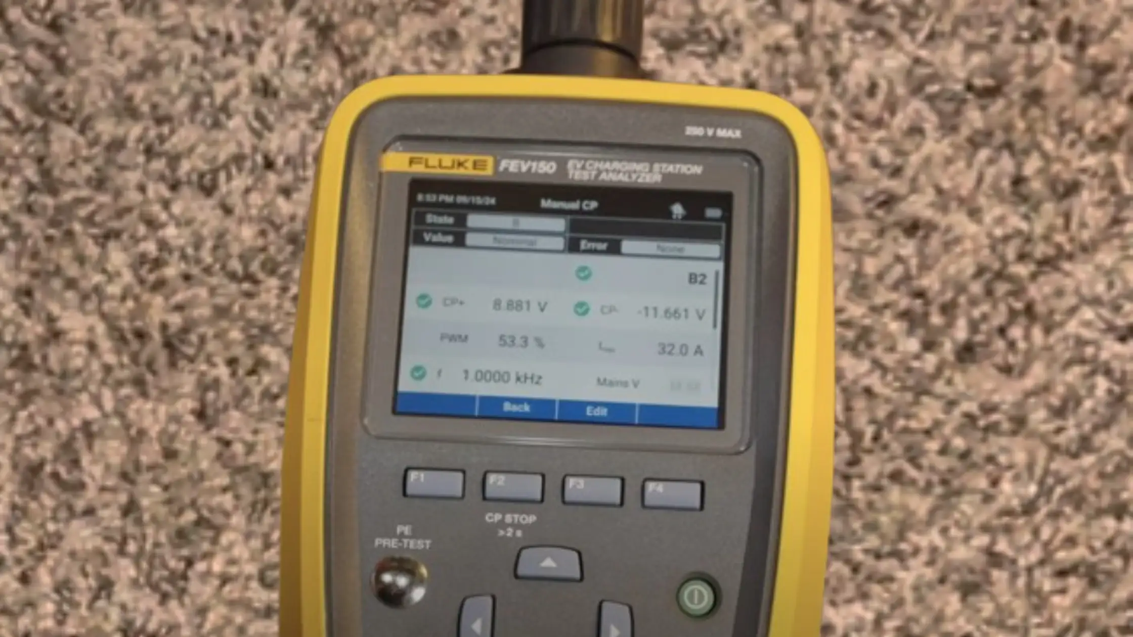
It supports a wide range of home EV charger tests, including a Protective Earth (PE) pre-test to ensure no hazardous voltage is present, visual inspection prompts, GFCI trip tests at both 6 mA and 20 mA ground fault thresholds, and nominal voltage measurements. The analyzer also performs automatic control pilot (CP) testing with waveform analysis, manual CP control, proximity pilot verification, error condition simulations, and an advanced EV charging GFCI test, making it one of the most comprehensive EVSE testing tools in our test bench.
As our testing capabilities continue to expand, we plan to incorporate a dedicated power analyzer to evaluate electrical quality in even greater detail, including power factor, harmonic distortion, and overall system efficiency.
Environmental Testing
For now, we conduct environmental tests using practical but improvised methods. When a charger’s datasheet specifies an operating range, say, down to -22°F or up to 122°F, we place the unit in a chest freezer or use a space heater to bring it to the required temperature before beginning a charging session.
That said, our current methods aren’t repeatable or standardized. As we grow, we plan to invest in a dedicated temperature and humidity chamber to run controlled environmental tests across a full range of conditions.
We also aim to incorporate IP testing capabilities for water and dust ingress, enabling us to evaluate durability against IEC or NEMA standards. These upgrades will let us go beyond anecdotal testing and deliver more rigorous data on how well EV chargers survive extreme heat, cold, moisture, and debris exposure over time.
Safety and Fault Simulation
Safety is central to our EV charger evaluation process, not just for confirming compliance, but for ensuring real-world protection for both users and vehicles. Each branch circuit on our test bench is equipped with integrated GFCI protection and dedicated overcurrent breakers.
We routinely stress these systems by introducing overload conditions, simulating high-resistance ground faults, and applying abnormal voltage events to observe how reliably a charger detects and shuts down during unsafe operation.
To deepen our evaluations, we use the Fluke ST120+ GFCI tester to validate ground-fault protection functionality across 120V and 240V configurations. For insulation integrity, ground, and dielectric breakdown testing, we rely on the Associated Research (SCI) Omnia series HiPot testers, allowing us to assess whether a charger’s internal components withstand elevated voltages without leakage or failure, essential in identifying latent safety risks.
When testing smart EVSEs that claim layered fault detection or vehicle-integrated safety features, we deploy the Autel MaxiSys Ultra EV Diagnostic System. This tool helps us verify whether the vehicle registers or responds to fault conditions, providing insight into charger-to-EV communication protocols and system-level fault handling.
Recently, we’ve added the Haefely Axos 5 surge generator to simulate lightning strikes, switching transients, and power grid anomalies. This allows us to assess how chargers respond to high-energy impulses and transient events, which are increasingly relevant as EVSEs move into higher amperage ranges.
By combining real-world fault simulation with lab-grade diagnostic instruments, we provide a level of safety testing that surpasses datasheets, enabling readers to understand not only whether a charger meets code but also how it behaves when pushed to its limits.
Ground-Fault Protection: NEC Compliance and What’s Changing
Our reviews are aligned with the National Electrical Code (NEC), which currently mandates the following:
NEC 625.54 (2023) requires GFCI protection for all receptacles used to power EV chargers. This applies exclusively to plug-in installations (e.g., NEMA 14-50 or 6-50), not hardwired chargers.
Hardwired EVSE units do not currently require GFCI protection unless specifically mandated in the manufacturer’s installation instructions, such as Tesla’s Wall Connector v3, which includes an internal CCID20 device, not a standard Class A GFCI, though the manual uses the term “GFCI” loosely. This distinction is not aligned with strict NEC definitions.
NEC 210.8(F) also requires GFCI protection for all outlets up to 50A located outdoors or in garages. Depending on local enforcement, this can extend to hardwired EVSEs, especially if they are installed in a garage or outdoor setting.
However, the 2026 NEC update is set to close the current gap by requiring GFCI protection for all EVSEs, including hardwired units. This shift will have widespread implications for residential and commercial installations, especially for electricians and inspectors working in jurisdictions that rapidly adopt new code cycles.
We plan to update our review criteria and product recommendations to reflect the 2026 changes as they become official. This will ensure our readers stay ahead of evolving compliance standards, particularly important for homeowners, builders, and installers seeking code-compliant solutions with long-term reliability and safety in mind.
By integrating lab-grade instruments with code-conscious fault testing, our approach goes beyond checkbox compliance. We help users understand how a charger behaves in the presence of faults, voltage instability, or insulation failure, delivering expert-level insight where it matters most: safety.
Data Logging and Automation
Right now, our data logging process is manual. We track metrics using timers, screenshots, handwritten logs, and spreadsheets. While this approach is accurate, it’s time-intensive and leaves room for inconsistencies during long-term or endurance tests.
To streamline and scale our testing, we plan to build a PC-connected automation and data logging system. This system will allow us to script full charge cycles, automatically collect and chart power usage, temperatures, and event logs, and generate detailed reports across multiple test runs. This will give us a higher level of consistency, repeatability, and transparency across all of our reviews.
Why We Built a Custom EV Charger Test Bench
At Electric Vehicle Geek, we believe EV charger reviews should be rooted in evidence, not marketing claims or first impressions. That’s why we developed a custom test bench: to bring consistency, precision, and technical depth to every evaluation.
This purpose-built platform is the backbone of our review process. It enables us to conduct repeatable, real-world testing across a wide range of charging scenarios, so our recommendations reflect performance, not assumptions. By investing in professional-grade infrastructure, we ensure our readers get trustworthy, data-driven insights that go far beyond typical consumer reviews.
Ensuring Consistency and Fair Comparisons
One of the biggest challenges in reviewing EV chargers is creating a level playing field. By standardizing the testing environment, including the power supply, wiring configuration, and test conditions, we eliminate variables that could distort performance results. This allows us to make fair, direct comparisons between chargers, giving readers a clear picture of how each unit performs under identical conditions.
Testing for the Real World
Our bench is designed to accommodate a wide range of residential AC EV charging scenarios, including Level 1 and Level 2 chargers, both plug-in and hardwired. Whether it’s a 120V portable unit or a 240V wall-mounted system, we’re able to simulate realistic installation environments and charging behaviors. This comprehensive setup ensures that our reviews reflect how these chargers will perform in everyday use.
Independent Verification of Manufacturer Claims
With precision monitoring equipment integrated into our setup, we can verify key performance metrics such as power output, charging speed, and efficiency. This independent validation helps us confirm or challenge manufacturer claims, adding an essential layer of credibility to our reviews. Our goal is to provide honest, evidence-based assessments that readers can rely on.
Built-In Safety, Built-In Trust
At Electric Vehicle Geek, EV charging safety isn’t just a feature of our testing process; it’s at the core of our mission. From the beginning, our goal has been to help users make safe, informed choices when selecting and installing EV chargers and accessories.
Our custom EV charger test bench is engineered to meet rigorous electrical safety requirements. Each branch circuit is built using NEC-compliant wiring methods, properly rated overcurrent protection devices (OCPDs), correctly sized conductors, and certified EV charging components. We use only high-quality, UL-listed accessories, the same ones we recommend in our reviews, to ensure alignment between our lab environment and real-world installations.
This setup protects both our team and equipment during testing, while allowing us to thoroughly evaluate each EV charger’s internal safety features. We assess smart EV charging safety features, overcurrent protection, ground fault detection, voltage drops, surges, grounding and bonding continuity, thermal behavior, and fault tolerance under consistent, load-calibrated EV charging conditions.
Our test bench and evaluation procedures adhere to the latest standards set by the National Electrical Code (NEC), National Electrical Installation Standards (NEIS), National Fire Protection Association (NFPA), Electric Vehicle Infrastructure Training Program (EVITP), and Occupational Safety and Health Administration (OSHA). We also follow proper load calculation methods, site planning practices, and manufacturer installation guidelines to ensure that every test and recommendation reflects safe, compliant EV charging practices.
By making EV charging safety an integral part of our lab design, we deliver reviews that do more than compare products; they help prevent hazards, protect property, and promote long-term reliability for EV chargers, accessories, and their installations.
Stay Ahead of Our EV Charging Tests
Curious which EV chargers and charging accessories are coming next to our test bench? Plan your next upgrade with our expert reviews and detailed guides. Explore upcoming tests and updates to existing reviews, and never miss a product update.

James Ndungu is a certified EV charger installer with over five years of experience in EVSE selection, permitting, and installation. He holds advanced credentials, including certification from the Electric Vehicle Infrastructure Training Program (EVITP) and specialized training in EV charging equipment and installation, as well as diplomas in EV Technology and Engineering Fundamentals of EVs. Since 2021, James has tested dozens of EV chargers and accessories, sharing expert insights into the latest EV charging technologies.