This guide is a detailed, technically honest account of how we integrated the Tesla Universal Wall Connector with our off-grid solar system on a limited budget, the decisions we made, and the hard-won lessons that came out of the process.
For us, we needed to charge four NAC-supported electric vehicles using our off-grid solar system, and this is what drove us to consider the Tesla Universal Wall Connector as the best off-grid EV charger for us – we will explain why later, don’t worry.
Charging multiple electric vehicles on a property with limited solar power is less straightforward than most installation guides suggest. When you add the constraint of living off-grid, where every amp drawn from your solar power energy storage system is precious, the decisions you make during system design carry serious consequences for both day-to-day reliability and long-term solar EV charging electric vehicle branch circuit health.
Table of Contents
- Why the Tesla Universal Wall Connector?
- Our Property: The Constraints That Drove Every Decision
- Our Installation Options
- Daisy Chaining Multiple Wall Connectors: Step-by-Step
- Conclusion
Why the Tesla Universal Wall Connector?

Tesla Universal Wall Connector Review Best Overall
We recommend the Tesla Universal Wall Connector as the best home solar EV charger, as it offers more advanced smart EV charging features including solar EV charging features than any other home EV charger we have tested, including the Gen 3 Wall Connector.
As we look at home EV charger trends in 2026, one clear shift is the rise of multi-vehicle households. More homes now have two or more electric vehicles, creating strong demand for smart chargers that can manage multiple cars without requiring major panel upgrades.
The Tesla Universal Wall Connector with Group Power Management (GPM) stands out, efficiently balancing multiple EVs on a single circuit, making it ideal for solar or limited-power setups.
GPM is a firmware-level feature that allows multiple Tesla Universal Wall Connector units to communicate with each other over your local network and dynamically redistribute available current among vehicles as they connect and disconnect.
For homes with a single electric vehicle and abundant grid power, this distinction is not as important. But for an off-grid property running multiple EVs on a constrained solar-battery system alongside heavy household loads (HVAC, pumps, kitchen appliances), the GPM feature is not a luxury. It is what makes the installation viable.
We recommend the Tesla Universal Wall Connector as the best home solar EV charger for the Tesla Model Y Long Range, Tesla Model 3 Long Range, Hyundai Ioniq 5, Tesla Cybertruck, Ford Mustang Mach-E, Ford F-150 Lightning, Chevrolet Equinox EV, Kia EV6, Tesla Model S, Chevrolet Blazer EV, Chevrolet Silverado EV, and Hyundai Ioniq 6, and other NACs supported electric vehicles.
The Tesla Universal Wall Connector also supports a wide range of non-Tesla vehicles via J1772 adapters, which future-proofs the installation as your EV fleet evolves.
Our Property: The Constraints That Drove Every Decision
Before describing the installation, it is important to clarify the constraints we were working under, as these directly explain why we chose the Tesla Universal Wall Connector as our ideal off-grid EV charger and guided every technical decision we made.
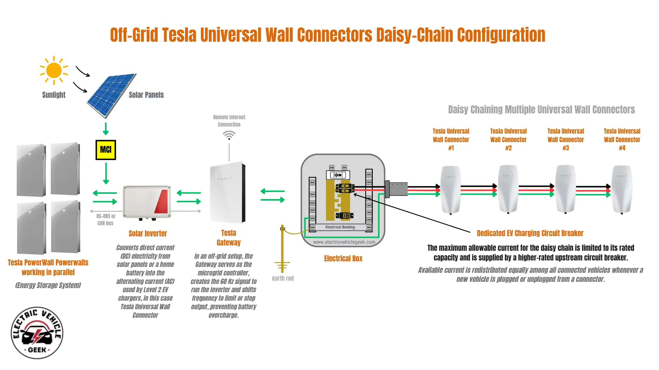
- Off-grid solar system: No utility grid connection. Our only power source is solar panels, a battery bank, and a diesel generator for backup. Every watt has a cost.
- Limited solar capacity: Our array is sized for total household energy independence, not for the luxury of dedicated high-power EV charging. This is the norm for off-grid systems, which are designed holistically rather than around any single load.
- Multiple EVs: Four electric vehicles that require overnight charging, often simultaneously. Sequential charging was impractical given our morning departure schedules.
- Competing home loads: HVAC, a well pump, a chest freezer, workshop tools, and general lighting all share the same inverter capacity. Our off-grid EV charging electric vehicle branch circuit does not get priority by default.
Our Installation Options
When it comes to multiple EV charger installation, even in solar EV charging, the Tesla Universal Wall Connector supports two fundamentally different electric vehicle branch circuits (Individual Dedicated Branch Circuits and Shared Branch Circuit).
Understanding the trade-offs between electric vehicle branch circuits – both Individual Dedicated Branch Circuits (IDBCs) and Shared Branch Circuits (SBCs) – is crucial in multi-vehicle installations, especially for managing EV charging loads under limited power, such as solar systems.
Option A: Individual Dedicated Branch Circuits
Each charger has its own branch circuit, so available power is not limited by a shared upstream breaker. This setup allows the system to capture short-duration solar surplus in real time and deliver maximum charging speed. With grid support or sufficient battery storage, higher coincident loads are manageable without compromising system stability.
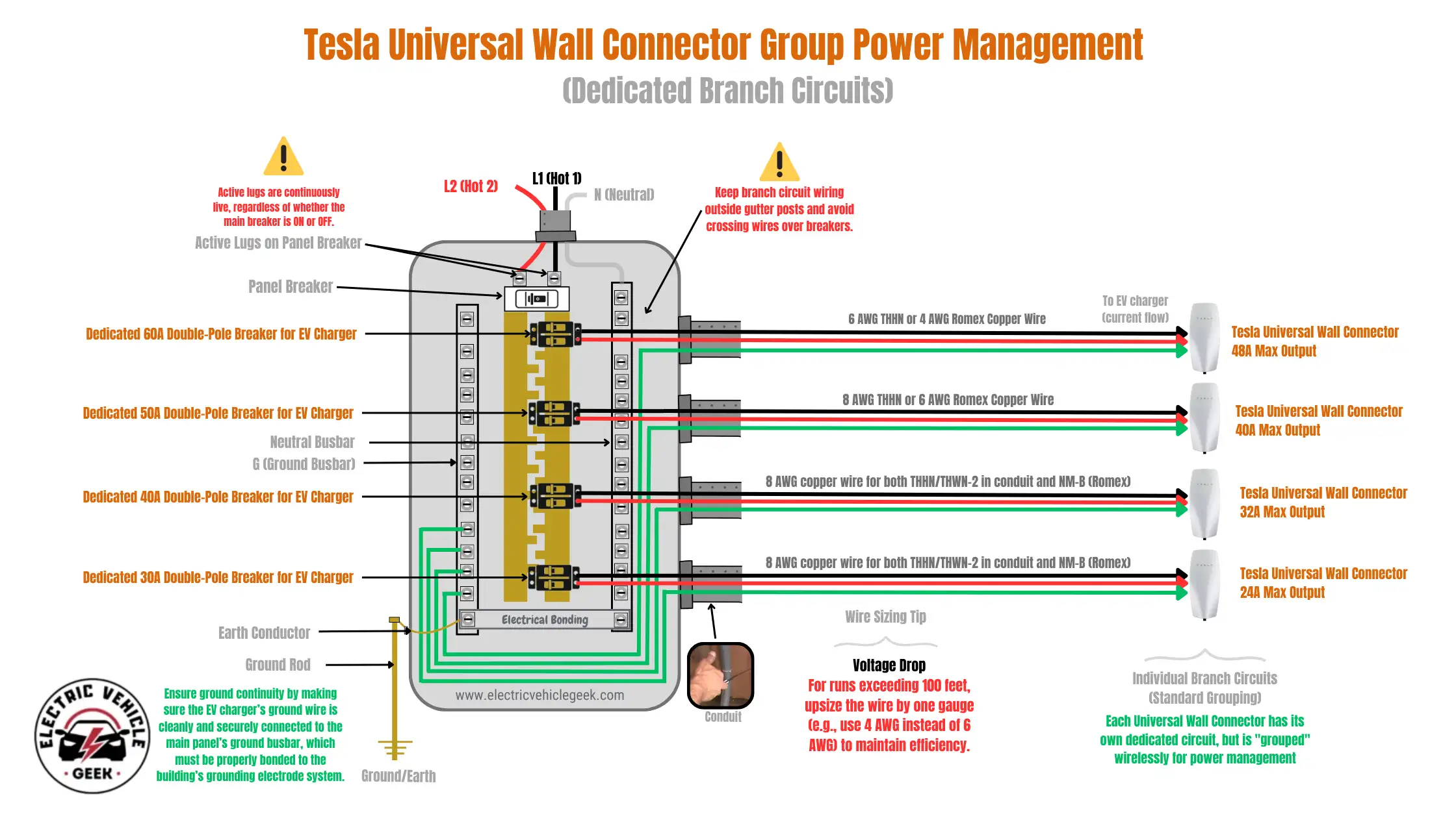
Each Tesla Universal Wall Connector is connected to its own dedicated circuit and breaker, typically 60A for a 48A continuous draw. The units still communicate via GPM over Wi-Fi, but each operates independently and can draw up to its rated amperage simultaneously, provided the energy source can supply it.
This approach is ideal when:
- You have a large grid-tied solar system that regularly produces extra power.
- You want to use Self-Powered Mode to make the most of every kWh from the sun.
- Your electrical panel has enough capacity and space for multiple large breakers.
- EV charging is on a dedicated solar sub-array, separate from other home loads.
Option B: Shared Branch Circuit (Daisy Chaining) – Our Choice
The shared upstream OCPD sets a firm limit on total continuous current, enforcing a predictable site load in kW and preventing coincident EV demand from exceeding inverter output or battery limits. This approach prioritizes battery survival and whole-home energy security over peak charging speed.
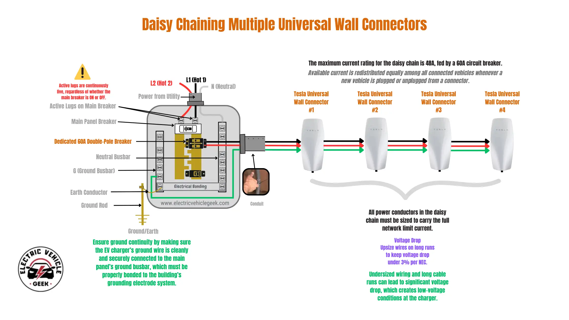
All Tesla Universal Wall Connector units operate on the same circuit and breaker. GPM software automatically manages current distribution within this ceiling, rebalancing within seconds whenever a vehicle is added or removed
This is the correct choice when:
- Solar capacity is limited and shared among all home loads.
- You need a hardware-level safeguard to prevent the battery from being overdrawn, which is especially important off-grid.
- Budget or panel space limits the number of high-amperage breakers you can install.
- Your energy strategy uses Backup Reserve mode to protect battery health.
Why We Chose the Daisy Chain – And Why You Might Not
The decision to daisy-chain our solar EV charging installation for multiple EVs was both a budget-friendly choice and the technically correct solution for our setup. Here’s why:
The Off-Grid Battery Bank Is the Binding Constraint
A grid-tied home with a Powerwall has a safety net: if the EVs overdraw the battery, the grid absorbs the difference. Off-grid, there is no safety net. If four Tesla Universal Wall Connectors simultaneously draw at 48A each (a theoretical 192A total), and solar production is low or it is nighttime, you are placing a continuous 192A EV charging load on the off-grid solar system. In our case, we do not have the luxury of that level of sustained power draw.
Although most solar EV chargers allow amperage adjustment, mixed current ratings complicate power sharing and site load management. Dynamic load-balancing systems operate most efficiently when all chargers have similar maximum output; otherwise, available capacity cannot be evenly distributed, and lower-rated units often end up underutilized while higher-power stalls attract the majority of users.
The daisy chain’s dedicated single 60A breaker is a physical protection mechanism in an off-grid EV charging system. No software misconfiguration, no GPM firmware bug, no accidental setting can push the EV chargers above 60A; the breaker enforces the limit.
Backup Reserve Mode Aligns with Shared Circuit Design
In our off-grid EV charging system, charging will occur primarily at night, drawing from our energy storage system alongside other household loads. To manage this, we plan to implement load balancing across our off-grid home system, including our daisy-chained electric vehicle branch circuit.
In this mode, the Powerwall maintains a set state-of-charge threshold before allowing EV charging. This means:
- Home loads are always prioritized, which happens before we go to sleep.
- EV charging only begins when the battery is healthy enough to sustain it
- The physical current capacity from the shared breaker further limits the rate at which EVs can deplete the reserve
Together, these two constraints (one in firmware and one in hardware) form a robust, layered protection strategy for solar EV charging that is significantly more reliable than software-only limits, particularly in multi-charger installations.
When Individual Circuits Would Have Been Correct
If we only had a small number of EV chargers, for example, two units within the comfortable capacity of our available solar power system, individual circuits would have been the superior choice. With fewer chargers and adequate available power, dedicated circuits allow each unit to operate at its full potential without the constraints of shared power distribution.
Likewise, if we had a dedicated solar sub-array used exclusively for EV charging, with no competition from household loads, individual circuits would again be the preferred design. The same applies to a grid-tied system with a large Powerwall and abundant solar production, where Self-Powered Mode benefits from the ability of individual circuits to capture short-duration high-surplus “spikes” without wiring bottlenecks.
In an off-grid system with shared solar resources, however, the daisy-chain configuration remains the clear winner.
Installation Decision Matrix
Use this matrix to select the correct architecture based on energy availability, system type, and load priority, not just wiring preference.
| Electric Vehicle Branch Circuit Design | Recommended Mode | Best Use Case |
|---|---|---|
| Individual Dedicated Circuits | Self-Powered | Grid-tied homes, large hybrid systems, solar-abundant properties, and high-performance EV charging |
| Shared Feeder / Daisy-Chained Chargers (OUR SETUP) | Backup Reserve | Off-grid systems, battery-limited hybrid systems, and multi-charger installations with competing household loads |
Daisy Chaining Multiple Wall Connectors: Step-by-Step
Step 1: Energy Storage System Sizing and EV Charging Load Calculation
Before touching a single wire, we performed a complete load audit to determine the required energy storage system (ESS) size and available capacity for EV charging. We documented every load (continuous draw, peak draw, and time-of-use patterns) to establish a realistic power and energy budget.
Our inverter’s continuous output rating sets the hard ceiling for all coincident loads. From that value, we subtracted the maximum simultaneous household demand (with HVAC representing the worst case) to determine the true available headroom for EV charging.
That remaining capacity dictated both the ESS sizing requirements and the circuit design, including the amperage setting of the Tesla Universal Wall Connector and the breaker size for the shared, daisy-chained EV feeder.
In our case, the calculated headroom was just over 60A, allowing full utilization of the Tesla Universal Wall Connector without exceeding the inverter’s continuous output limit.
Step 2: Running the Shared Branch Circuit
We installed a single 60A branch circuit from the main distribution panel to the garage mounting location of Tesla Universal Wall Connector #1. Because EV charging is a continuous load, EV charger wire sizing for this circuit was calculated in accordance with the 125% rule, making conductor selection non-negotiable from both a safety and thermal-performance standpoint.
For our 60A daisy chain electric vehicle branch circuit, that meant #6 AWG copper (THHN/THWN-2) in conduit for the ungrounded conductors, paired with a #10 AWG copper equipment grounding conductor, which provides ample ampacity for a 60A EV circuit over typical residential run lengths.
Aluminium conductors may be used where allowed, but they must be upsized (typically #4 AWG) and terminated with AL-rated connectors. We recommend solid copper wiring for EV charger installations because it offers superior conductivity, lower voltage drop, and long-term reliability.
From Wall Connector #1, the daisy-chain feeder continues to Wall Connectors #2, #3, and #4 using the same ampacity-rated conductors. Each Tesla Universal Wall Connector includes dedicated pass-through terminals specifically engineered for this topology, making it a fully supported installation method – not our geeky field improvisation.
This feature (daisy-chaining) is not available on the Tesla Gen 3 Wall Connector, and it is a key reason we chose the Tesla Universal Wall Connector for our multi-EV solar setup, which has both budget and limited power constraints.
This shared feeder architecture creates a single, physically enforced 60A ceiling for the entire EV charging group, ensuring the combined continuous load can never exceed the inverter’s available output while still allowing intelligent power sharing between all four chargers.
Step 3: Configuring Group Power Management
Group Power Management (GPM) configuration is performed through the Tesla app after each Tesla Universal Wall Connector is provisioned to the same Wi-Fi network (2.4GHz only). The process:
- Register each Tesla Universal Wall Connector individually through the Tesla app using its QR code or serial number.
- Navigate to the Energy Site settings and assign all Tesla Universal Wall Connectors to the same Power Sharing Group.
- Set the Network Limit – this is the critical value that must match your branch circuit breaker’s continuous rating (80% of breaker size by NEC code). For our 60A breaker, this is 48A total for the group.
- Designate one Tesla Universal Wall Connector as the controller unit and the others as follower units.
- Test the rebalancing behavior by plugging vehicles in one at a time and observing the current redistribution in the app’s live view.
Step 4: Energy Mode Configuration
With GPM operational, we configured our battery management system to operate in a mode equivalent to Tesla’s Backup Reserve. Our charge controller is programmed to:
- Block EV charging when battery state-of-charge drops below 40%
- Allow EV charging to resume only when SOC exceeds 50% (hysteresis prevents chattering)
- Reduce EV charging to a trickle rate during evening hours when solar recovery is impossible
- Pause EV charging entirely if generator operation is triggered by a low-battery alarm.
Conclusion
Using the Tesla Universal Wall Connector with a solar power system is very powerful. When done correctly, it can make charging multiple electric vehicles possible on limited solar power, while keeping your home energy system stable and reliable.
But “done correctly” means understanding your actual power limits. Off-grid systems are very different from grid-tied systems. Installation choices that work well for a grid-connected home can create reliability and hardware problems on an off-grid, battery-powered system.
For our off-grid property, a shared branch circuit (the daisy chain) was the best solution. It is the safest, most reliable, cost-effective method, and it works best with limited solar energy shared among multiple loads.
Note: We recommend hiring a Tesla Certified Installer to set up your Tesla Universal Wall Connector and select the right solar EV charging accessories and features for your system.

James Ndungu is a certified EV charger installer with over five years of experience in EVSE selection, permitting, and installation. He holds advanced credentials, including certification from the Electric Vehicle Infrastructure Training Program (EVITP) and specialized training in EV charging equipment and installation, as well as diplomas in EV Technology and Engineering Fundamentals of EVs. Since 2021, James has tested dozens of EV chargers and accessories, sharing expert insights into the latest EV charging technologies.