An EV charger ground fault is an unwanted flow of current from a hot conductor to ground inside the EV supply equipment (EVSE) or the electric vehicle. It triggers the charger’s built-in personnel protection circuit, opens the contactors, and stops the charging session within milliseconds.
This guide covers the physics, NEC and UL rules, internal fault types, troubleshooting steps, and advanced installation strategies that prevent ground faults in residential and commercial EV charger installations.
Unlike a standard household GFCI, an EV charger uses a charge circuit-interrupting device (CCID) tuned to the leakage profile of an electric vehicle. Understanding how this device works, why it trips, and how to prevent nuisance tripping is key to safe and reliable EV charging.
This guide builds on our parent EV Charger Earthing Guide and our guide to testing EV charger earth leakage and faults.
Table of Contents
- Foundations of EV Safety: Why Grounding Alone Is Not Enough
- NEC 625 and UL 2231: The Regulatory Landscape
- The Anatomy of an EV Charger Ground Fault
- Troubleshooting the Ground Fault Detected Error
- Advanced Installation Strategies for Professionals
- Recommended Accessories for EV Charging Ground Fault Prevention
- Future Proofing: Bidirectional Charging and V2G Faults
- Conclusions
Foundations of EV Safety: Why Grounding Alone Is Not Enough
A solid earthing system provides a low-resistance path for fault current back to the source, but it does not, on its own, prevent a person from being shocked.
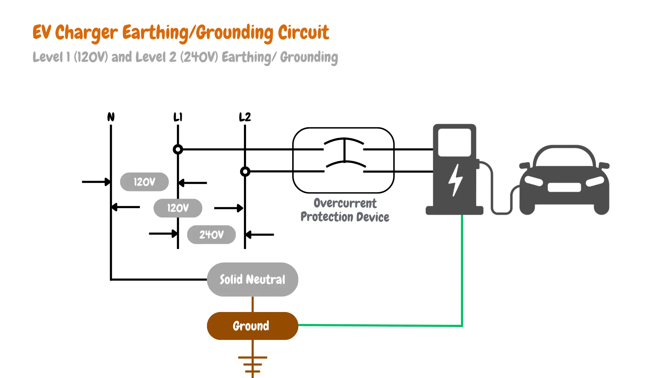
The current still flows for the time it takes the protective device to trip. In an EV install, where a 240V split-phase circuit feeds a vehicle parked outdoors on damp pavement, that response time has to be measured in milliseconds, not seconds.
This is why every modern EVSE pairs the equipment grounding conductor (EGC) with an active leakage detection device.
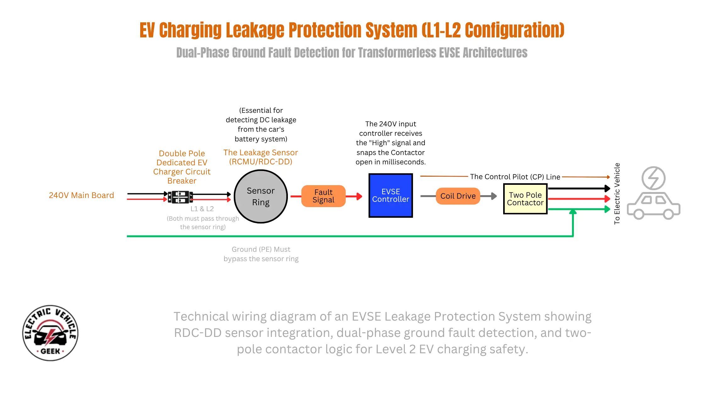
The diagram above explains how a Level 2 EV charging station safely manages power delivery and fault protection during electric vehicle charging. The system uses an RDC-DD sensor to monitor for dangerous AC and DC leakage currents and immediately stop charging if a fault is detected. The EVSE controller communicates with the vehicle through the Control Pilot (CP) signal to confirm that the connection is secure and charging conditions are safe before power is enabled. A two-pole contactor disconnects both power lines during a fault, while the protective ground connection safely carries stray current away from the vehicle and charging equipment.
The Physics of Ground Faults
In a healthy EV charger circuit, every milliamp that flows out on the line conductors returns on the neutral or the opposite line. The two currents cancel inside the charger’s current transformer, and the differential reading sits near zero. A ground fault breaks that balance. Some of the outgoing current finds an unintended path, usually through worn insulation, water in the connector, or a damaged cable. It returns to the source through the equipment grounding conductor or, in the worst case, through a person.
In a high-voltage EV system, leakage is not just a 60Hz AC problem. The vehicle’s onboard charger, the inverter, and the EMI filters in both the EVSE and the car all create high-frequency switching currents. A small portion of these currents couple to chassis ground through Y-class capacitors. This is normal and harmless, but it adds up to a baseline leakage of several milliamps before any real fault is even present. The CCID has to ignore that baseline and still catch a true fault.
Touch Potential Risks: How a 240V Fault Can Electrify a Vehicle’s Chassis.
If the line conductor inside an EV charger or the vehicle’s onboard charger contacts an exposed metal surface, that surface can sit at line voltage relative to remote earth. With a 240V split-phase EVSE, that means up to 120V from chassis to true ground on each leg. A person standing on damp ground or wet concrete becomes part of the return path the moment they touch the car or the charger handle.
The medical literature treats anything above 30mA AC at 60Hz as the start of the ventricular fibrillation zone for a typical adult. The let-go threshold, at which a person can still pull free from the source, lies between 6 and 16 mA. These numbers drive every threshold in EV charger safety: 5 mA for unprotected paths, 20 mA for EGC-verified paths, and 6 mA for smooth DC residual current.
Grounding vs. Bonding: The Equipment Grounding Conductor (EGC) for EVSE
Grounding sends fault current to earth. Bonding ties all metal parts together so they sit at the same potential. The equipment grounding conductor (EGC) is the green or bare copper wire that carries fault current from the EVSE chassis, the conduit, and the metal outlet box back to the bonded neutral at the service panel.
In an EV charger circuit, the EGC has two jobs. It carries fault current long enough for the upstream breaker to trip, and it carries the small ground monitor sense current the EVSE uses to verify that the ground path is intact before it energizes the contactors. If the EGC is broken, undersized, or terminated to a separate, unbonded rod, the CCID will refuse to close the relays. We size the EGC per NEC Table 250.122 based on the breaker, not the charger amps. See our guide on choosing the right EV charger wire gauge for the full breakdown.
NEC 625 and UL 2231: The Regulatory Landscape
Two documents govern EV charger ground fault protection in the United States. NEC Article 625 sets the installation rules for when GFCI protection is required, for sizing circuits, and for wiring bidirectional systems. UL 2231 sets the equipment rules: what the personnel protection circuit inside the EVSE must do, when it must trip, and how it must verify the ground path. Every UL-listed EV charger sold in the US has to meet both.
NEC 2023 and 2026 Updates: GFCI Requirements for Level 1 and Level 2 Circuits
Section 625.54 of the 2023 NEC requires that all receptacles installed for EV charging equipment connection have ground-fault circuit-interrupter protection for personnel. This applies to every NEMA 5-15, NEMA 5-20, NEMA 6-50, and NEMA 14-50 outlet used to feed a portable or fastened-in-place charger. Hardwired EVSE is the exception: the outlet feeding a hardwired charger does not need upstream GFCI unless the manufacturer specifies it, because the listed CCID inside the unit already provides personnel protection.
Section 625.60, also added in the 2023 cycle, covers bidirectional EVSE used for vehicle-to-grid power export. Standard residential GFCI breakers are not rated for backfeeding, so 625.60 effectively requires V2G systems to be hardwired with internal CCID protection. Section 230.67 and Article 242, also strengthened in 2023, now require type 1 or type 2 surge protective devices (SPDs) on dwelling-unit services, which protect the sensitive CCID monitoring circuit downstream of every EVSE.
The 2026 NEC cycle continues the same trajectory: tighter labeling for EV branch circuits, clearer load calculation rules in Article 220.57, and stronger language around bidirectional systems in 625.48 and 625.60. None of the 2026 changes weaken the 625.54 GFCI requirement for receptacles, so installers should continue to plan every cord-and-plug install around a GFCI-protected outlet, even if the charger has its own CCID.
UL 2231-1 and UL 2231-2: How Personnel Protection Differs from a Residential GFCI
A standard residential GFCI is built to UL 943 and trips at 4 to 6mA of differential current. It is a one-size-fits-all device. The CCID inside an EV charger is built to UL 2231-1 (system requirements) and UL 2231-2 (component requirements), and it is tuned specifically for the leakage profile of an electric vehicle.
UL 2231 lets the manufacturer choose between two threshold levels. The first is the sensitive 5mA path. The second is a higher 20 mA threshold, allowed only if the EVSE also includes a ground monitor/interrupter (GMI) circuit that continuously verifies the integrity of the EGC. If the GMI detects an open, deteriorated, or increased impedance on the ground path, the EVSE must disconnect the line, neutral, and the contactors that feed the vehicle, regardless of the leakage reading.
CCID20 vs. CCID5: Why EV Chargers Use a 20mA Trip Threshold
Most production Level 2 chargers in the US ship with a CCID20, not a CCID5. The reason is nuisance tripping. The Y-class capacitors in the vehicle’s onboard charger and the EVSE leak between 1 and 5 mA to chassis ground during normal operation. A 5mA device sees that as a fault and trips before the session even starts. A 20 mA device is above this baseline but well below the 30 mA fibrillation threshold, which is why UL 2231 allows it, but only when the GMI monitors the ground path.
CCID5 vs. CCID20: At a Glance
| Parameter | CCID5 | CCID20 | Residential GFCI |
|---|---|---|---|
| AC trip threshold | 4 to 6 mA | 15 to 20 mA | 4 to 6 mA |
| Ground monitor required | No | Yes (GMI) | No |
| Standard | UL 2231 | UL 2231 | UL 943 |
| Typical use | Portable Level 1 sets | Wall-mounted Level 2 EVSE | Bathrooms, kitchens, garages |
This is also why stacking a residential GFCI breaker upstream of a CCID20 charger almost always causes nuisance trips. The two devices race each other on every leakage event, and the 5mA device wins. We cover the fix later in the troubleshooting section. For background, see our guide on the EV charger circuit breaker that keeps tripping.
The Anatomy of an EV Charger Ground Fault
Not every ground fault error is the same fault. Modern EVSEs detect four distinct conditions, each with its own circuit, threshold, and diagnostic signature. Understanding which one your charger is reporting can tell you whether the problem is in the wall, the cable, or the car.
DC Leakage Injection: How 6mA of DC Can Blind a Type A GFCI
The vehicle’s onboard charger is a switch-mode power supply. When its filter capacitors degrade, or its IGBTs develop a short, a smooth DC residual current can leak back through the charging cable to ground. As little as 6 mA of smooth DC can saturate the iron core of a standard type A GFCI breaker. Once saturated, the core can no longer detect the alternating magnetic field of a real AC fault, and the breaker becomes blind to a life-threatening shock condition.
This is why modern EV chargers include a residual direct current detecting device (RDC-DD) per IEC 62955. The RDC-DD trips the contactors at 6mA of smooth DC, well before the upstream type A GFCI loses sensitivity. In US-built EVSEs, this DC sensitivity is built into the CCID itself: UL 2231-2 requires the CCID20 to detect a DC component of roughly 56.6 mA peak (40 mA × 1.414), which is the equivalent fault energy. If your installation includes an upstream AC-only RCD or GFCI, the EVSE’s internal RDC-DD is the only thing standing between a smooth DC fault and a person.
Isolation Faults: Insulation Breakdown in the High Voltage Battery
Inside the vehicle, the high-voltage traction battery floats with respect to the chassis. A dedicated isolation monitor measures the resistance from each battery rail to the chassis and reports a fault if that resistance drops below roughly 100 ohms per volt. Causes include coolant leaks onto bus bars, vibration-damaged insulation, road-salt intrusion, and degraded service plug seals.
During AC charging, the EVSE does not directly measure traction battery isolation. Instead, the vehicle reports any isolation fault to the EVSE through the J1772 or NACS communication line, and the EVSE shuts down the session. The driver sees a ground fault error on the charger, but the actual fault is in the car. This is why a charger that trips at one site but works fine at another, or trips on one car but not another, is almost always reporting a vehicle-side problem.
Relay Welding Detection: Internal Faults That Prevent the Charger from De-Energizing
Every Level 2 EVSE uses two main contactors to switch the AC supply to the vehicle. They are mechanical, and like all mechanical contacts, they can weld closed under heavy arcing or after thousands of switching cycles. UL 2231 requires the EVSE to verify, on every plug-in event, that the contactors actually open when commanded. The charger does this by sensing voltage on the load side while the contactors are commanded open. If the sensed voltage is above roughly 24V RMS, the controller declares a welded relay fault.
A welded relay is reported as a ground fault on most consumer chargers because, from the user’s perspective, the symptom is identical: the charger refuses to start, the indicator turns red, and the unit will not reset. A welded contactor is also why the dual-contactor design exists in the first place. If both contactors have to fail closed before the vehicle is energized, the probability of a hot output during a non-charging event drops by orders of magnitude.
Pilot Signal Interference: When Communication Errors Mimic Ground Faults
The J1772 control pilot is a 1kHz square wave that swings between +12V and a state-dependent low rail. The vehicle pulls a resistor across the pilot to signal its presence and its state. Noise on this line, from a corroded J1772 plug, a pinched cable, or EMI from a nearby variable frequency drive, can corrupt the duty cycle the EVSE measures. The EVSE interprets this as the vehicle requesting an unsafe state and trips the contactors.
On most chargers, this presents as a ground fault error or a generic charger fault, even though the EGC is fine and the leakage detector never tripped. The fix is almost always mechanical: clean the pilot pin, reseat the cable, and check that the vehicle’s charge port is free of debris.
Troubleshooting the Ground Fault Detected Error
Once you understand the four fault types above, troubleshooting becomes a process of elimination rather than guesswork. Start with the cheapest, most reversible checks and work outward toward the panel.
The Red Light Guide: Decoding Manufacturer Flash Codes
Every major EVSE brand publishes a flash code chart for its status indicator. The fault code tells you which subsystem reported the trip, which lets you skip the wrong part of the diagnostic tree.
- Tesla Wall Connector: solid red plus a code in the app. Code 7 indicates a ground assurance fault (an open or high-impedance EGC). Code 8 indicates a CCID trip. The Tesla Gen 3 Wall Connector review covers full diagnostics.
- ChargePoint Home Flex: a red ring with a flashing pattern. Three red flashing points indicate a ground fault. Five points to a relay welding event. Seven points to a pilot signal fault.
- JuiceBox 40 and Pro 40: a red LED with the fault written out in the JuiceNet app. The most common entry is GFCI Lockout, which requires unplugging from the vehicle and the wall outlet to reset.
- Autel MaxiCharger: a fault code on the OLED screen plus a Bluetooth login in the app. The Autel MaxiCharger 80A review walks through every code in the table.
The Nuisance Tripping Matrix
A real ground fault is an electrical hazard. A nuisance trip is the protective system doing its job in response to a non-hazardous condition. Knowing the difference saves an enormous amount of time. Below are the four causes we see most often in the field.
Moisture and Corrosion: J1772 Handle and Charge Port
Water in a J1772 or NACS connector is the single most common cause of intermittent ground faults. Even a small amount of moisture between the pilot pin and the proximity pin lowers the effective resistance the EVSE measures and shifts the apparent state of the vehicle. Salt residue, common in coastal and snow-belt installs, accelerates this. The fix is dry contact deoxit, a tight-fitting holster, and a charger pedestal that drains away from the connector.
Double GFCIs: Why a GFCI Breaker Plus a CCID Charger Equals Constant Trips
A residential GFCI breaker trips at 4 to 6mA. A wall-mounted Level 2 charger trips its CCID20 at 15 to 20mA. They share the same neutral path, so the same 4 mA leakage event affects both, and the 5 mA device wins every race. The result is a charger that will not stay online for more than a few minutes.
The fix depends on the install. For hardwired Level 2 EVSE, NEC 625.54 does not require an upstream GFCI. Replace the GFCI breaker with a standard breaker of the same rating and let the listed CCID handle personnel protection. For cord-and-plug installs, the GFCI receptacle is required by code; in this case, choose a charger model that uses series-pass leakage detection rather than a duplicated CCID, or accept the trade-off and reset both devices when they trip.
Grid Noise: Solar Inverters and Variable Frequency Drives
Grid-connected solar inverters and variable-frequency drives in shop equipment inject high-frequency common-mode current into the utility neutral. A small fraction of this current returns through the EGC instead of the neutral, and the CCID reads it as differential leakage. Symptoms include trips that correlate with solar production peaks at midday or with HVAC compressor cycles in the early evening.
The cleanest fix is to put the EV charger on a dedicated circuit fed from the main panel rather than a subpanel that also feeds the inverter or the VFD. A common-mode choke at the EVSE input can knock down the residual high-frequency current by an order of magnitude.
Test Equipment: EVSE Adapters, Multimeters, and Insulation Testers
Most ground fault complaints can be resolved with three pieces of test gear. Each one targets a different layer of the system.
- J1772 / NACS test adapter (also called an EVSE tester): plugs into the charger handle and emulates a vehicle. Use this to confirm the EVSE energizes correctly with no car attached. If the adapter charges normally and your car does not, the fault is in the vehicle, not the EVSE.
- Digital multimeter: for verifying line-to-ground voltage, neutral-to-ground voltage, and the integrity of the EGC. Neutral-to-ground voltage above 2V on a residential 240V circuit suggests an undersized neutral or a loose lug at the panel.
- Insulation tester (Megger): A 500V or 1000V insulation tester measures the resistance between each conductor and ground over the full length of the run. A reading below 1 megohm on any conductor indicates degraded insulation that will eventually cause a ground fault. We use the Megger MIT400 series for residential work and document readings before and after every service call.
- Micro-ohm meter: for measuring the resistance of the EGC and the bonding jumpers. The Vici VC480C+ reads from 0.1 µΩ to 2000 Ω, well below the resolution of a standard multimeter. We covered the full procedure in our guide to testing EV charger earth leakage and faults.
Advanced Installation Strategies for Professionals
Most field-ground fault complaints trace back to installation decisions made at the start of the job. The strategies below remove the conditions that cause nuisance trips before the charger ever sees a vehicle.
Hardwiring vs. Plug-In: Reducing Points of Failure
A hardwired EV charger eliminates two failure modes that plug-in installations cannot: the receptacle itself, which can loosen and arc over thousands of plug cycles, and the upstream GFCI breaker required by 625.54 for cord-and-plug installs. Hardwired EVSE relies on its internal CCID for personnel protection, which is purpose-built for the leakage profile of an EV.
Recommendation: for any 40-amp or higher Level 2 install, hardwire the charger to a non-GFCI breaker sized per NEC Table 250.122 and let the listed CCID handle personnel protection. For 30-amp and lower installs that the homeowner may want to take with them when they move, the cord-and-plug option remains valid, but expect occasional GFCI trips and educate the customer to reset both devices.
Subpanel Balancing: Managing Harmonic Distortion and Unbalanced Loads
EV chargers are not the only source of high-frequency current on a residential panel. LED drivers, variable speed pool pumps, mini-split heat pumps, and solar inverters all inject harmonics that ride on the neutral. When these loads share a subpanel with an EVSE, harmonic current appears as differential leakage at the CCID.
- Balance Level 2 EV loads across both legs of the panel. A 48 amp charger pulls 48 amps on each leg simultaneously, so panel balance is mainly about the rest of the loads, not the charger itself.
- Avoid sharing a neutral between an EV branch and any non-linear load (LED lighting, switch-mode power supplies). The shared neutral path returns a harmonic current that the CCID will read as leakage.
- If the install includes a solar inverter, locate the EV charger circuit upstream of the inverter on the same bus, not downstream. Downstream placement puts the inverter’s common-mode current directly through the charger’s CCID.
- For commercial sites, specify a K-rated transformer feeding the EV subpanel. K-13 is the standard for moderate harmonic content; K-20 is for sites with multiple DC fast chargers.
Surge Protection (SPD): Protecting Sensitive CCID Monitoring Circuits
The CCID’s current transformer and the GMI sense circuit are sensitive to transient overvoltage. A 6kV ring-wave from a nearby lightning strike or a utility switching event can permanently damage the toroid, leaving the EVSE either tripping constantly or, worse, blind to real faults. NEC Article 242 has required type 1 or type 2 SPDs at the service entrance for dwelling units since the 2020 cycle, and this protection is the first line of defense for every downstream EVSE.
For commercial and fleet installs, add a type 3 SPD at the EVSE itself. The Siemens BoltShield FSPD140 is our standard recommendation for residential service entrances; for charger-side protection, a DIN-rail-mounted type 3 device sized to the local utility’s let-through voltage gives the CCID a fighting chance during a transient event. We cover this in detail in our EV charger safety features guide.
Recommended Accessories for EV Charging Ground Fault Prevention
After running ground fault diagnostics on hundreds of home EV charger installations, we noticed the same root causes keep popping up: weak surge protection at the service entrance, undersized neutrals on shared panels, water in the connector, and stacked GFCI devices. Most of these problems can be prevented with four classes of accessories. Below are the products we use on our own jobs and recommend to our readers, grouped by the role they play in keeping the CCID happy.
1. Upstream Protection and Power Quality
EV chargers are continuous loads. The quality of the power feeding them matters as much as the charger itself. A clean, surge-protected service is the foundation of every install we sign off on.
Whole-Home Surge Protective Device (SPD)
We recommend the Square D HEPD80 for residential service entrances and the Eaton Ultra series for sites with three-phase or higher service. Both are UL 1449 Type 1 listed and mount directly next to any brand of load center.
Why we use it: the CCID inside every EV charger is an active monitoring board with a small toroidal current transformer and a sensitive analog front end. A 6kV ring wave from a distant lightning strike or a utility switching event can fry that board, causing the charger to fail its power-on self-test permanently. We have replaced more than a few EVSE units that lost their CCID after a single storm. An 80kA Type 1 SPD at the service entrance pays for itself the first time it absorbs a transient instead of letting it through to the charger.
Section 230.67 of the 2023 NEC now requires Type 1 or Type 2 SPDs at every dwelling-unit service, so this is no longer optional for new installations. For more on how surge protection ties into the rest of the EV charger safety stack, see our guide on EV charger safety features.
EV-Specific Circuit Breakers
For the dedicated EV branch circuit, we use brand-matched, continuous-duty breakers that match the load center: Siemens QP series for Siemens panels, Schneider Homeline series for Square D Homeline panels, and Eaton BR series for Eaton BR panels.
Why we use it: A generic replacement breaker rated for the same amperage will technically pass inspection, but its thermal trip curve may not be tuned for an 80% continuous load. We have seen “phantom” trips that customers blamed on the EV charger turn out to be cheap third-party breakers tripping due to heat after 90 minutes of charging. Brand-matched breakers, sized per our EV charger circuit breaker selection guide, end this problem entirely.
2. Diagnostic and Testing Tools
Most ground fault complaints can be resolved on a single service call if you have the right test gear in the truck. The two tools below are the ones we reach for first.
EVSE Tester Adapter (J1772 / NACS to Multimeter)
We use the Tera EVSE Tester for J1772 for residential calls and the Fluke FEV100 for commercial work. Both plug into the charger handle and emulate a vehicle so you can run a full session without a real EV connected.
Why we use it: When a customer reports a ground fault, the first question is whether the fault is in the EVSE, the cable, or the car. An EVSE tester answers that in under a minute. The better units also let you manually trigger a leakage event so you can verify that the CCID actually trips at its rated 20 mA threshold. This is the only practical way to test the active part of the leakage detector without plugging in a real vehicle. We covered the full bench procedure in our guide to testing EV charger earth leakage and faults.
Clamp-On Leakage Current Meter
We use the Fluke 368 FC for high-end work and the Hioki CM4001 as a budget alternative. Both can resolve leakage current down to about 10 microamps with a 40mm shielded jaw.
Why we use it: A standard clamp meter cannot read the 1 to 5mA baseline leakage that a healthy EV charger produces. The Fluke 368 FC can. Clamping it around the line conductors at the EVSE while a vehicle is charging tells you, in real time, whether you are looking at a nuisance trip caused by the car’s EMI filters (steady 1 to 4mA) or a hard fault in the wiring (drifting upward over the session). It also reveals harmonic leakage from solar inverters and variable-frequency drives that no other tool can detect.
We also keep a Vici VC480C+ digital micro-ohm meter in the truck for resistance checks on the equipment grounding conductor. Together, these three tools cover almost every diagnostic question a ground fault error can raise.
3. Smart Load and Leakage Management
In 2026, the cost of a panel upgrade can exceed the cost of the EV charger itself. The accessories below let you stay within the existing service while still avoiding the trips that come from running too close to the main breaker limit.
External Energy Monitor with Dynamic Load Balancing
We recommend the Emporia Vue 3 Home Energy Monitor or, even better, the bundled Emporia Pro EV Charger, which integrates the Vue 3 directly into the charger with built-in PowerSmart Load Management. The Sense Home Energy Monitor is the next best alternative if you already have a different charger brand.
Why we use it: the Vue 3 reads your home’s total load 3,000 times per second through two 200A current transformers on the main feeders. When the water heater, dryer, or HVAC compressor turns on, the monitor signals the charger to throttle down before the main breaker trips. This is dynamic load balancing, and it is what lets a 48A Level 2 charger live on a 100A or 125A service that would otherwise need a panel upgrade.
Tripped main breakers also cause ground-fault errors because the EVSE loses both the line and the GMI sense reference simultaneously. Preventing the main trip in the first place prevents the ground fault error from ever showing up.
Automated Circuit Splitter (Shared Outlet Solutions)
For renters and homeowners who cannot run a dedicated circuit, we recommend the NeoCharge Smart Splitter or the Lectron NEMA 14-30 Splitter to share a dryer outlet between the dryer and an EV charger.
Why we use it: A smart splitter has internal logic that ensures only one device draws power at a time. The dryer takes priority when it runs; the charger resumes charging when the dryer cycle ends. From a ground-fault standpoint, the splitter also keeps a clean, single ground path for whichever device is active, preventing the ground loops you would otherwise get when running two appliances in parallel through a single neutral.
Stick to UL-listed splitters only. The cheap, unbranded versions sold online lack internal thermal fuses, and we have seen them melt the receptacle they are plugged into. See our plug-in EV charging outlet covers and lockouts section for compatible options.
4. Physical Protection and Maintenance
Environmental factors cause more intermittent ground faults than wiring errors do. The accessories below address the leading culprits: moisture, salt, and dirty contacts at the plug interface.
NEMA 4X Rated Enclosures
For coastal, snowbelt, or high-humidity installs, we step up from the default NEMA 3R rating to NEMA 4X. Most Level 2 chargers in this category, including the Autel MaxiCharger, the Emporia Pro, and the Tesla Universal Wall Connector, ship with a NEMA 4 housing. For pedestal installs, we add a NEMA 4X-rated junction box and weatherproof EV charger pedestal.
Why we use it: Salt-laden coastal air and road-salt spray cause creepage, which is the slow growth of conductive tracks across a circuit board surface. Even at sub-millimeter levels, creepage produces leakage currents in the milliamp range, which is more than enough to trigger a CCID20. A NEMA 4X enclosure seals the PCB from this contamination and extends the charger’s reliable service life.
Contact Cleaner and Dielectric Grease
We use DeoxIT D5 to clean J1772 and NACS pins, then apply a thin film of dielectric grease only on the proximity and pilot pins. CRC QD Electronic Cleaner is our backup when DeoxIT is unavailable.
Why we use it: oxidation and dirt on the J1772 pilot pin add resistance to the 1kHz pilot signal, which the EVSE reads as a corrupted state machine and reports as a ground fault. A 30-second wipe with DeoxIT clears this completely. Do not use silicone-based dielectric grease on the L1 or L2 power pins; it can carbonize under heavy current. Reserve grease for the smaller communication pins only.
Future Proofing: Bidirectional Charging and V2G Faults
Vehicle-to-grid (V2G) and vehicle-to-home (V2H) are the next frontier for ground fault detection. When the car becomes a power source instead of a load, the directional assumptions baked into a traditional CCID no longer hold.
V2G Integration Risks: Managing Ground Loops During Bidirectional Energy Exchange
During V2G export, current flows from the vehicle out to the grid through the same conductors that fed the car during charging. The CCID still reads differential current, but the source of any leakage is now the vehicle’s inverter, not the utility. If the home’s grounding system and the utility’s grounding system are at different potentials, even a few volts of difference, a ground loop forms, and the CCID sees it as leakage. The result is an export session that trips offline minutes after it starts.
The 2023 NEC, in section 625.60, addresses this by requiring bidirectional EVSE to be hardwired and listed for power export. Standard residential GFCI breakers are not rated for backfeeding and will fail open under reverse current. Any V2G install should include a single point of common bonding between the home’s main grounding electrode system and the EVSE chassis, with no parallel paths through subpanels or auxiliary rods.
Smart Diagnostics: Using OCPP to Identify Leakage Trends Before a Trip
Open Charge Point Protocol (OCPP) is an open standard that enables a charging station to report telemetry to a back-end management platform. Most commercial EVSE supports OCPP 1.6J or 2.0.1. The protocol exposes the CCID’s running leakage reading as a metric value, not just a binary trip event.
With OCPP telemetry collected over weeks or months, you can plot baseline leakage per session per vehicle. A vehicle whose baseline drifts from 2 mA to 8 mA over a six-month window is on a trajectory toward a CCID trip, and you can schedule service before the driver experiences a roadside failure. Fleet operators use this data to flag vehicles with degrading onboard chargers, water-damaged charge ports, or failing isolation. For residential customers, the same trend data is available through the manufacturer’s app: JuiceNet, Autel Charge, the Tesla app, and ChargePoint Home Flex all expose at least a basic version of this leakage history.
Conclusions
EV charger ground faults are not the same as residential GFCI trips. They are detected by a purpose-built CCID tuned to the leakage profile of an electric vehicle, governed by UL 2231 on the equipment side and NEC 625 on the installation side.
- CCID20 is the standard threshold for wall-mounted Level 2 EVSE. It allows 15 to 20 mA of differential current before tripping, paired with a ground monitor that continuously verifies the EGC.
- A smooth DC residual current of 6 mA can trip a type A GFCI. Modern EVSE includes an RDC-DD per IEC 62955 to catch this before it turns off the upstream protection turns off.
- Most ground fault errors in the field are not real faults. They are nuisance trips from stacked GFCIs, moisture in the connector, harmonic current from solar or VFDs, or pilot signal noise.
- Hardwiring Level 2 chargers eliminates the most common causes of nuisance trips and is permitted by NEC 625.54 without an upstream GFCI.
- V2G and bidirectional installations require careful attention to grounding to prevent ground loops, hardwired connections per NEC 625.60, and, ideally, OCPP telemetry to catch leakage trends before they become trips.
For diagrams, NEC tables, and the full installation procedure, read our EV Charger Earthing Guide. For step-by-step ground path verification with a micro-ohm meter and a Megger, see our guide to testing EV charger earth leakage and faults. For breaker and wire sizing across the full charger amperage range, our EV charger circuit breaker selection guide and EV charger wire gauge guide cover every common configuration.

James Ndungu is a certified EV charger installer with over five years of experience in EVSE selection, permitting, and installation. He holds advanced credentials, including certification from the Electric Vehicle Infrastructure Training Program (EVITP) and specialized training in EV charging equipment and installation, as well as diplomas in EV Technology and Engineering Fundamentals of EVs. Since 2021, James has tested dozens of EV chargers and accessories, sharing expert insights into the latest EV charging technologies.